
Manual


IS 12 / IGA 12 Manual Controls and Instalaltion 17
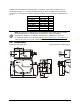
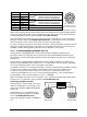
Connecting to RS485 interface
Half-duplex mode:
A1 and A2 as well as B1 and B2 are
bridged in the 12-pin round
connector of the connecting cable,
to prevent reflections due to long
stubs. It also safeguards against the
interruption of the RS485 Bus
system should a connecting plug be
pulled out. The master labels mark
the connections on the RS485
converter. The transmission rate of
the serial interface in Baud (Bd) is
dependent on the length of the
cable. Values between 2400 and
115 kBd may be set.
The baud rate is reduced by 50% when the transmission distance is doubled (see 5.10 kBaud
(baud rate)). Typical cable length for 19200 Bd is 2 km.
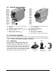
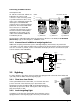
3.1.3 Connection of additional analyzing devices
Additional analyzing instruments (such as LED digital display instruments) only need to be
connected to a power supply and the analog outputs from the pyrometer. Another Instrument,
such as a controller or printer, can be connected to the display in series as shown below (total
load of resistance max. 500 Ohm).
yellow
LED digital display
Controller
Power supply
green
brown
white
230 V ~
24 V DC
°C
Writer
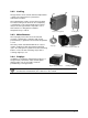
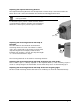
3.2 Sighting
For exact aiming to the object, the pyrometers are equipped with a thru-lens view finder and
optionally with an additional laser targeting light.
3.2.1 Thru-lens view finder
In the optimized thru-lens view finder, a circle marks the exact
position and size of the measuring spot. Pyrometers with
temperature ranges exceeding 1500 °C are equipped with an
adjustable eye protection filter. Turning the ocular changes the
filter from bright to dark.
3.2.2 Laser targeting light
In addition to the thru-lens view finder, the instruments can be
equipped with a laser targeting light. The laser point marks the
Eye
protection
filter
Terminator 120 Ohm
A
B
S
K
A
B
C
D
J
G
F
E
H
M
L
K
A
B
C
D
J
G
F
E
H
M
L
K
A
B
C
D
J
G
F
E
H
M
L
DGND
B1
A2
B2
A1
DGND
B1
A2
B2
A1
DGND
A2
B2
A1
B1
Master
Pyrometer 32
e.g. address 31
Pyrometer 2
e.g. address 01
Pyrometer 1
e.g. address 00