
Manual

IS 12 / IGA 12 Manual Instrument Settings 22
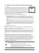
3) ENT:
If a parameter is changed with the arrow keys
,
the new value
must be confirmed by pushing the ENT key. If it is not confirmed
with ENT, the instrument will operate with the previous
parameter value. If no key is pressed for approx. 30 s, the display
changes to the temperature indication.
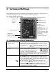
Limit contacts:
Two limit switches can be set. If the measuring temperature
exceeds the adjusted limit contact temperature, the LED S1 or S2
displays the switch status.
Scale °C or °F:
The LED indicates the temperature scale in °C or °F.
Parameter indicator:
LED’s indicate which pyrometer parameter is selected for reading
or changing.
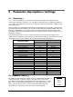
4.3 Factory settings
Emissivity (
) = 1,000
Exposure time (t
90
/ s) = 0,00
Clear time (t
CL
) = 0,00
Sub range (from / to) same as temperature range
Analog output (0 / 4 mA) = 0 ... 20 mA
Limit contacts = end of temperature range
Hysteresis = ±2 °C
scanning angle (only IS 12-S and IGA 12-S): 4°
scanning frequency (only IS 12-S and IGA 12-S): 5 Hz
Temperature display (
°C / °F
) = °C
Interface (RS) = RS232
Address (ADR) = 00
Baud rate (kBaud) = 19.2 kBd
Test current output (10 mA) = off
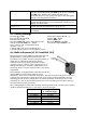
4.4 Built-in Scanner (IS 12-S and IGA 12-S)
The pyrometers IS 12-S and IGA 12-S with fixed optics are
equipped with a scanning mechanism built into the
pyrometer housing which moves the measuring beam up
and down. In combination with the pyrometer's
maximum value storage (peak picker), the scanner is
optimally used for scanning of thin oscillating wires, for
finding scale-free spots on heavily scaled surfaces or for
measuring small, hot objects whose position is not exactly
determined.
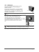
All instruments are equipped with a thru-lens view finder
and an additional laser targeting light for exact
alignment to the position of the measuring object. The thru-lens view finder doesn’t follow the
scanning mirror movement; it always shows the center of the scanning amplitude. The laser
targeting light follows the scanning mirror movement and always shows the position of the
measuring spot. The moving measuring beam does not increase the spot sizes due to the very
fast exposure time of the pyrometers.
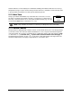
The scanning length increases with increasing measuring distance. An overview of the scanning
length at the different distances of the optics is shown in the table.
distance a
scanning distance at
4° scanning angle
a = 80 mm
5.6 mm
a = 160 mm
11.2 mm
a = 250 mm
17.5 mm
a = 660 mm
46 mm
a = 1300 mm
91 mm
a = 5600 mm
391 mm
Scanning
amplitude