MANUAL IMPAC Pyrometer IS 6 Advanced / IGA 6 Advanced
Confidential Information The material contained herein consists of information that is the property of LumaSense Technologies and intended solely for use by the purchaser of the equipment described in this manual. All specifications are subject to change without notice. Changes are made periodically to the information in this publication, and these changes will be incorporated in new editions.
Contents 1 General Information...................................................................................................... 5 1.1 Information about the user manual..................................................................... 5 1.1.1 Legend ................................................................................................................. 5 1.1.2 Terminology ........................................................................................................ 5 1.2 Safety ..
.4 Response Time (t90) .............................................................................................. 23 4.5 Clear Peak Memory (tCLEAR) ................................................................................... 24 4.5.1 Single and Double Storage Modes .................................................................... 24 4.5.2 Clear Time Settings............................................................................................ 24 4.6 Analog Output .......................
1 General Information 1.1 Information about the user manual Congratulations on choosing the high quality and highly efficient IMPAC IS 6 Advanced / IGA 6 Advanced pyrometer. This manual provides important information about the instrument and can be used as a work of reference for installing, operating, and maintaining your IS 6 Advanced / IGA 6 Advanced pyrometer.
Disassembly of the instrument is not allowed. The warranty is VOID if the instrument is disassembled, tampered with, altered, or otherwise damaged without prior written consent from LumaSense Technologies; or if considered by LumaSense Technologies to be abused or used in abnormal conditions. The Windows compatible software was thoroughly tested on a wide range of Windows operating systems and in several world languages.
Technical Support can be contacted by telephone or email: Santa Clara, California · Telephone: +1 408 727 1600 or +1 800 631 0176 · Email: support@lumasenseinc.com Frankfurt, Germany · Telephone: +49 (0) 69 97373 0 · Email: support@lumasenseinc.com Erstein, France · Telephone +33 (0)3 88 98 98 01 · Email support@lumasenseinc.com 1.
To ensure consistent document formatting, this page was intentionally left blank.
2 Introduction 2.1 Appropriate use 2.2 Scope of delivery The IMPAC IS 6 Advanced / IGA 6 Advanced are short wave infrared temperature measuring devices with digital signal processing. They are used for non-contact temperature measurements on metals, ceramics, graphite, etc. with a temperature range between 250 and 3000 °C. Pyrometer, PC adjustment, and evaluation software InfraWin, works certificate, and operating instructions.
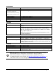
Environment Protection Class: Operating Position: Ambient Temperature: IP 65 IEC 60529 (value in mated condition) Any 0 to 70 °C at housing Note: During operation the instruments will warm up and might reach an intrinsic temperature of up to 58 °C Storage Temperature: Relative Humidity: Weight: Housing: CE-Label: Interface Connection: Display (in rear cover): Parameters: -20 to 80 °C Non condensating conditions 0.
2.4 Dimensions IS 6 Advanced / IGA 6 Advanced with the view finder IS 6 Advanced / IGA 6 Advanced with laser sighting 2.
2.6 Accessories (optional) Numerous accessories guarantee easy installation of the pyrometer. The following overview shows a selection of suitable accessories. You can find the entire accessory program with all reference numbers in Chapter 8, Reference numbers. 2.6.1 Mounting Mounting brackets are available for safe mounting and alignment of the pyrometer to the measuring object. Mounting angle 2.6.
support can be equipped with a quartz window for vacuum applicationsIt may consist of an equipment rack, flange, and an open or closed ceramic tube. The equipment rack can be equipped for vacuum applications with a fused silica. 2.7 Transport, Packing, Storage With faulty shipping, the instrument can be damaged or destroyed. To transport or store the instrument, please use the original box or a box padded with sufficient shock-absorbing material.
To ensure consistent document formatting, this page was intentionally left blank.
3 Controls and Installation 3.1 Electrical Installation The IS 6 Advanced / IGA 6 Advanced is powered by a voltage of 24 V DC ± 25% (ripple < 50 mV). It is important to ensure correct polarity when connecting the device to the power supply. To meet the electromagnetic requirements (EMV), a shielded connecting cable must be used. LumaSense offers connecting cables, which are not part of the standard scope of delivery. The shield of the connecting cable has to be connected only on the pyrometer’s side.
Pin K A L B H J G F C D E M Color white brown green yellow Function +24 V DC power supply 0 V DC power supply + IAusg. analog output – IAusg. analog output Targeting light activate / deactivate via gray external switch (bridged with K) External clearing of max.
Terminator Pyrometer 1 e.g. Address 00 Pyrometer 2 e.g. Address 01 Pyrometer 32 e.g. Address 31 RS485 Bus System 3.1.4 Connection of Additional Units For temperature indication of the pyrometer, LumaSense offers pure indicators (series DA 4000). LumaSense also offers indicators with features to change pyrometer parameters (DA 6000 and DA 6000-N) as well as a fast digital PID controller PI 6000.
3.2 Sighting The IS 6 Advanced / IGA 6 Advanced can be purchased with Through-Lens Sighting (viewfinder) or with a Laser Targeting Light. These sighting options allow you to easily align the pyrometer to the measuring object. 3.2.1 Viewfinder The IS 6 Advanced / IGA 6 Advanced can be equipped with a viewfinder which offers throughlens sighting. The viewfinder is true-sided and parallax-free. A circle marks the position of the measuring spot, but not the exact spot size.
Never look directly into the laser beam. The beam and spot can be watched safely from side. Also, make sure that the beam will not be reflected into eyes of people by mirrors or shiny surfaces. The laser targeting light can be switched on and off by pressing the button of the rear cover of the housing. Push button for Laser Targeting Light Note: The laser warning signs on the pyrometer should be easily viewable at all times, even after it has been installed.
Aperture D for all temperature ranges is 13 to 15 mm with the aperture being the effective diameter of the lens. This is dependent on the optical setting. The largest value applies to a very small measuring distance, while the minimum value applies to the largest measuring distance. Measuring Distance a [mm] 210 300 500 800 1300 2000 5000 IGA 6 Advanced IS 6 Advanced 0.6 0.9 1.5 2.3 3.7 5.
The LED Distance Indicator Light (labeled mm) will turn red and the approximate focused measuring distance in mm will automatically be shown on the Digital Display for a few seconds after making an adjustment using the Focus Adjustment Set Screw. Note: Turning the focus adjustment screw counterclockwise will shorten the measuring distance. Turning the focus adjustment screw clockwise will lengthen the measuring distance.
To ensure consistent document formatting, this page was intentionally left blank.
4 Settings / parameter descriptions The pyrometer is equipped with a wide range of settings for optimal adaptation to the required measuring condition and to measure the temperature correctly. All settings can be read and set only in the pyrometer parameters window of the software InfraWin. Adjusting the settings at the instrument is not possible (detailed description of the software see Chapter 5, Software InfraWin). Selecting the pyrometer parameters window shows the current settings of the pyrometer.
The response time is set using the InfraWin software or by using the UPP Data Format commands. When the setting is set to min., the IS 6 Advanced / IGA 6 Advanced operate using a time constant of approximately 120 µs. The response time can be extended to 0.01 s; 0.05 s; 0.25 s; 1 s; 3 s; 10 s. Note: Settings for Response Time t90 min, 1 ms; 3 ms; 5 ms; 10 ms; 50 ms; 250 ms; 1 s; 3 s; 10 s 4.
10 ms…25,0 s If the clear time is set between 10 ms and 25.0 s, the maximum value is held in double storage mode. After the entered time, the value will be cleared alternately from one of the storages, while the value of the other storage is shown. EXTERN With the external clearing function, the storage operates in single storage mode. The values are immediately cleared from the storage by contacting the wires connected to pins J and K, if the EXTERN mode was selected.
Note: Only via own communication program with interface command (not possible with InfraWin, because InfraWin automatically detects a connected pyrometer): If parameters should be changed simultaneously on all pyrometers, the global Address 98 can be used. This allows you to program all pyrometers at the same time, regardless of the addresses that have already been assigned.
5 Software InfraWin The operating and analyzing InfraWin software is included with delivery of the pyrometer. In addition to allowing you to make parameter adjustments, the InfraWin software also provides temperature indication, data logging, and measurement analysis features. This section gives an overview about the functions of the software. It also provides a description of the individual icons found in the program's help menu.
5.4 Basic settings All preset values for the device can be displayed and modified, if necessary under the Devices/Parameters window. Changing an existing pyrometer setting can be accomplished by typing a value in an input box or by selecting a preset value from the list field. Choose the correct settings for your application from the displayed options. This window contains the parameter settings described in Chapter 4, Parameters. 5.4.1 Open/Save 5.4.2 1 measure… 5.4.3 Print 5.4.4 Close 5.4.
Len indicates the length of the answered data string, incl. Carriage Return (Chr(13)). In the lower part of the window, the connection with the preset baud rate can be checked. Here the command was sent 100 times with 19200 baud. It has taken 0.997 seconds without transmission errors.
Note: The measuring values of “measurement online trend” are automatically saved as "standard.i12". Should you need to edit the data later, you need to save the file as another .i12-file because old values are over-written when a new measurement is taken. Files from older program versions (.i10-files) can be opened and saved as .i12. 5.6 Listing (analyzing) For analyzing the measured values in this field, all measured data appears in a numeric list.
Note: The last reading is saved in the standard.i12 file and automatically appears in this form upon opening Listing or Trend output. Selecting file open with another file, the previous file will be overwritten and replaced by the standard.i12 file. 5.9 PC sampling rate (time interval between two measurements) This function sets a time interval. After each interval, one measured value is stored on the PC. Longer time intervals will result in creating smaller stored file sizes.
To ensure consistent document formatting, this page was intentionally left blank.
6 Maintenance 6.1 Cleaning the front window Since the device does not contain parts that require regular maintenance, the only regular maintenance required is periodic inspection of the front window for build-up of foreign particiles. If allowed to build up, the particles can influence the energy received by the instrument.
To ensure consistent document formatting, this page was intentionally left blank.
7 Data format UPPÒ (Universal Pyrometer Protocol) Software commands can be exchanged directly with the pyrometer through an interface using suitable communication software or by using the “Test” function located in the “Pyrometer Parameters” window of the InfraWin software package.
Description Command Parameters Response Time t90 AAezX X=0 to 9 0=min 1=1 ms 4=10 ms 7=1 s Temp Display °C or °F AAfhX Output: Device address AAgaXX XX=(00 to 97) 00 to 97=regular device addresses 99=global address with response Internal temperature (read) AAgt AAtm Answer: DDD 3 decimal digits (000 to 098 °C or 032 to 210 °F) gt=current temp. tm=maximum temp.
Description Command Parameters Device type / Software version AAve Answer: VVMMJJ VV=54 MM=Month JJ = Year of software version Communication Module/ software version in detail AAvc tt.mm.jj XX.YY tt = day; mm = month; jj = year; XX.YY = Software version Software version in detail AAvs tt.mm.jj XX.YY tt = day; mm = month; jj = year; XX.YY = Software version Note: the letter “l” means the lower case letter of “L”.
To ensure consistent document formatting, this page was intentionally left blank.
8 Reference Numbers 8.1 Reference numbers instrument Temperature Range With Laser Targeting With Viewfinder IGA 6 Advanced 250 to 2500 °C (MB 25) 3 914 010 3 914 020 IGA 6 Advanced 250 to 1800 °C (MB 18) 3 914 050 3 914 060 IS 6 Advanced 600 to 3000 °C (MB 30) 3 914 510 3 914 520 IS 6 Advanced 600 to 1800 °C (MB 18) 3 914 550 3 914 560 Ordering note: A connection cable is not included in scope of delivery and has to be ordered separately. 8.
3 846 260 Instrument's support (Series 5 & 6) 3 846 290 Instrument's support (Series' 5 & 6) with fused silica window 3 846 590 Vacuum support KF16 with quartz glass window 3 852 290 Power supply NG DC for DIN rail mounting; 100 to 240 V AC Þ 24 V DC, 1 A 3 852 550 Power supply NG 2D for DIN rail mounting; 85 to 265 V AC Þ 24 V DC, 600 mA with two settable limit switches 3 890 640 DA 4000-N: LED-digital display to be built into the switchboard 3 890 650 DA 4000: like DA 4000-N, but additionally
9 Troubleshooting Symptom No analog output even if the display shows a temperature above lower range limit Temperature reading differs between builtin display and external instrumentation Temperature readings are too low Probable Cause Reversed leads to IS 6 Advanced / IGA 6 Advanced Reversed leads to other instruments in the current loop Open circuit in lines connecting all instruments in current loop Total burden higher than 500 Ohms Insufficient supply voltage (See wiring diagram) Pyrometer output sett
Symptom Probable Cause Temperature readings are too high Faulty IS 6 Advanced / IGA 6 Advanced Electrical noise in lead wires caused by intense magnetic fields and/or improper selection of interconnecting cable and/or cable run in same conduit as AC power lines Lens or window clouding up Noisy readings (fast fluctuations) Laser Targeting Light fails Improper grounding of cable shield and/or IS 6 Advanced / IGA 6 Advanced housing (or cooling jacket) IS 6 Advanced / IGA 6 Advanced mounting not secure Ta
Index 1 Emissivity 23 1 measure… 28 F A Focus Adjustment Screw 20, 26 Focused Distance 26 Accesories 12 Air Purge 12 Analog Output 25 Aperture 20 Appropriate use 9 B Basic settings 28 Baud Rate 26 C Calibration 33 Laboratory 33 On-Site 33 Cleaning the front window 33 Clear Peak Memory 24 Clear Time Settings 24 Close 28 Connecting the pyrometer to a PC 16, 27 Connection cable 9 Connection of Additional Units 17 Connection to RS485 16 Cooling Jacket 12 D Data format UPPÒ 35 Device Address 25 Device S
Program start 27 Pyrometer Internal Temperature 26 Pyrometer parameters 23 W Warranty 5 R Reference numbers Accessories 39 Instrument 39 Reference Numbers 39 Repair 6, 7 Response Time 23 RS485 16 S Safety 5 Scaling Trend button 29 Scope of delivery 9 Service Request 6 Settings / parameter descriptions 23 Sighting 18 Single Storage Mode 24 Software InfraWin 27 Spot size calculator 31 Spot Sizes 19, 20 Spot sizes for non-focused distances 20 Storage 13 Storage Modes 24 Sub Range 25 Support 6 T Technical D