MANUAL Pearl Control Software
Pearl Control Software Data Acquisition and Analysis Software The material contained herein consists of information that is the property of LumaSense Technologies and intended solely for use by the purchaser of the equipment described in this manual. All specifications are subject to change without notice. Changes are made periodically to the information in this publication, and these changes will be incorporated in new editions.
No Liability for Consequential Damages In no event shall LumaSense or its suppliers be liable for any damages whatsoever (including, without limitation, damages for loss of business profits, business interruption, loss of business information, or other pecuniary loss) arising out of the use of or inability to use this LumaSense Technologies product, even if LumaSense Technologies has been advised of the possibility of such damages.
To ensure consistent document formatting, this page was intentionally left blank.
Contents 1 Introduction ................................................................................................................... 7 1.1 Information About the User Manual .................................................................... 7 1.2 Conventions ........................................................................................................... 7 1.3 System Requirements ........................................................................................... 7 1.
3 Capturing Images and Data ........................................................................................ 21 3.1 Data Selection ..................................................................................................... 21 3.2 Capturing Images ................................................................................................ 21 3.3 Copying Images ................................................................................................... 22 3.4 Saving Data.........
1 Introduction Pearl Control Software was designed by LumaSense Technologies, Inc., to control the Pearl camera or core. Users can adjust video settings, capture images, and use the software to assist in calibration. Pearl Control software is provided on a disc in a case. The latest version of the software and PDF documentation are included on the disc. 1.1 Information About the User Manual This manual provides all of the information you need to configure and use the Pearl Control software.
1.4 Camera and Core Configurations 1.4.1 Standard Camera and Core Configurations 1.5 About the Pearl Control Software Interface In general, most screens in the Pearl Control Software program are divided into five main sections: Title Bar Menu Bar Action Bar Workspace Area Information Bar 1.5.1 Title Bar The Title Bar, as you would expect with any Windows program, not only contains the program title, but also contains the minimize, maximize, and close program buttons. 1.5.
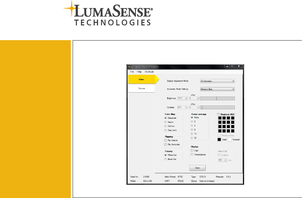
Ctrl + F: Toggle shutter. Opens and closes the shutter. Ctrl + R: Reread info. Reads all camera settings to ensure the displayed information is up to date. 1.5.3 Action Bar The Action Bar contains three tabs that allow you to configure settings, capture images and data, and calibrate your camera or core. Video The Video tab contains settings that affect the video and image quality. Capture The Capture tab contains tools that allow you to obtain images and data.
1.6.3 Configuring Settings The File Menu consists of five options: Save Program Settings Saves the program settings to a specified file. Saved settings include COM settings and save directory paths. Load Program Settings Loads program settings from a specified file. Program Settings Opens the program settings window. COM Settings This item controls which COM port the camera is connected on. Selecting this item will open a new window. Exit Program Exits the program.
3. Set the maximum number of COM ports the ‘Scan’ feature will use. To configure the COM settings: 1. Select COM Settings from the File Menu. 2. The COM Setup screen will appear. These settings control which COM port the camera is connected on. COM # displays a list of available COM ports. Baudrate for the camera connection, default is 115200. Note: If no COM ports are displayed, the program was unable to find an available port. Check your camera connection and settings. 3.
Connecting the RS232 cable to the OEM Module (left) and the Core (right). 2. Connect the other end of the RS232 cable to the computer USB. 3. Connect the power supply to the camera. Connecting the power to the OEM Module (left) and the Core (right). 4. Start the Pearl Control Software. When the software starts, it will scan your computer for a connected camera and load the settings for a found camera. If a camera is not found, a COM connection window will appear: a.
b. If you do not know the COM # and Baudrate, click Scan and the program will attempt to communicate with the camera/core. Once the camera is found, the software will load the camera settings. 5. The software is now ready for use. Note: If the camera is unable to connect, please refer to the Troubleshooting section.
To ensure consistent document formatting, this page was intentionally left blank.
2 Configuring Video Settings The Video Tab enables you to adjust the settings for images and videos. This chapter provides details on how to use these settings. Note: Only the Auto-Cal setting will save between camera power cycles – all other settings are temporary unless you click Save. 2.1 Display Settings 2.1.1 Display Adjustment Mode The Display Adjustment Mode determines if the Brightness and Contrast are adjusted automatically or manually by an operator.
2.1.3 Brightness You can manually adjust the brightness if you selected All Manual or Manual Brightness, Automatic Contrast for the Display Adjustment Mode. If you selected Offset Bias for the Automation Mode Settings, you can also set the offset. Slider Bar To edit the brightness: 1. Type a number (0 to 16383) in the box or use the slider bar to set the brightness. 2. Click Save. 2.1.
To set the default color map: 1. Click Video to view the Video Tab. 2. Select the desired Color Map. 3. Click Save. 2.3 Polarity The video polarity determines which values are used for high and low temperatures. The Pearl Control Software offers two options: White Hot Hot objects appear brighter, cold objects appear darker. Black Hot Cold objects appear brighter, hot object appear darker. (This is the default setting). To change the default polarity: 1. Click Video to view the Video Tab. 2.
2.6 Regional AGC Regional Automatic Gain Control (AGC) changes the automatic brightness and contrast to only react to certain regions in the image. Each square correlates to a region in the image. Clicking a square will toggle that region. Black squares are used for the regional AGC, white squares are unused. For instance, selecting the upper-left square will cause the brightness and contrast to adjust only when an object enters that region. To turn on/off Regional AGC: 1. Click Video to view the Video Tab.
Example: On the left, the hot object is outside of the selected region, so it is not used in adjusting the brightness and contrast. On the right, the object is now in the selected region and the brightness and contrast adjust for a better display. 2.7 Auto-Cal Automatic calibration (Auto-Cal) is used to keep the camera image quality looking good. If automatic calibration is active, the camera will calibrate when the temperature of the camera changes or the timer is exceeded.
2.8 Display Logo and Temperature You can have the software display a LumaSense logo and/or a camera temperature in the upper-left most area of the analog image. The image to the right shows both the LumaSense logo and the camera temperature. 1. While in Video Tab, click the box next to Logo and/or Temperature to enable the display item. 2. Click Save to finalize the selection.
3 Capturing Images and Data Single frames can be captured from the camera and downloaded to the Pearl Control Software. In addition to the live image, other types of images can be downloaded for diagnostic checks. Capture Tab Note: The Capture tab is not available on all versions of the Pearl Camera. Only versions 5.0.8 and newer support this feature. This tab is disabled for older versions. 3.
To change the color map when capturing an image: 1. Click Capture to view the Capture Tab. 2. Select the Color Map from the drop down menu. Note: This only changes the Color Map for the image shown. It has no affect on the Offset, Gain, and NUC maps. To Change the Default Color Map, see Section 2.2. 3.3 Copying Images To copy an image: 1. After capturing an image, click Copy. 2. The currently displayed image will copy to the clipboard, so that it can be pasted in other Windows programs. 3.
4 Using Calibrate Tab Features Note: The Calibrate Tab should only be unlocked by trained technicians. 4.1 Accessing the Calibrate Tab A password is required to unlock and access the Calibrate Tab and Reset Camera feature. To access the Calibrate Tab: 1. Click Help on the Menu Bar. 2. Select Advanced. 3. Type in the following password: engineer Note: The password is case-sensitive. 4. Click OK or press enter. 5. The Calibrate Tab will appear below the Capture Tab in the Action Bar.
4.1.1 Reset Camera Unlocking the Calibrate tab will also unlock the “Reset Camera” option in the Help menu. Reset Camera can be used to reset the various features in the camera. You may want to reset the camera if it is changed to an unusable state. To reset the camera: 1. Click Help on the Menu Bar. 2. Select Reset Camera from the drop down menu. 3. Click Yes to reset the camera. 4. To complete the reset, turn the camera off. When the camera is turned on again, it will reset its settings. 4.
4. Click on the Signal Section. 5. In the Integration Time section, you can either enter the desired value in the text box or use the slider bar to set the value. Slider Bar 6. Check the Status in the Information Bar to ensure the message “Updated integration time” appears. 4.2.2 Gain Gain adjusts the amount of gain used on the camera. Similar to Integration Time, increasing the gain value will increase the amount of signal the camera receives.
4.2.3 Correct Image The image should be corrected each time the integration time or gain are changed. This has the same operation as using the menu: Shortcuts > Correct Image. To correct the image: 1. Click Help and select Advanced from the drop down menu. 2. Enter the password: engineer 3. Click on the Calibrate Tab. 4. Click on the Signal Section. 5. Click Correct Image. 4.2.
6. Check the Status in the Information Bar to ensure the message Baudrate updated appears. Note: Baudrate changes will take effect the next time the camera is powered on. 4.3 Using the Gain Map A gain map (also known as a 2-point correction) can be used to improve the image quality. The gain map improves the image quality for a specific temperature range. In other words, if the scene changes temperature, the gain map becomes inadequate. Note: For most applications, a gain map is NOT recommended.
4.3.1 Reset Map Reset Map sets the gain map to its default state (blank). Use this button to reset an undesirable gain map back to the factory map. If additional pixels have been replaced, Reset Map will stop these pixels from being replaced. Pixel replacement will have to be repeated. Note: To keep this default state, the map will need to be saved once more to overwrite the saved gain map. To reset the map: 1. Click on the Calibrate Tab. 2. Click on Gain Map. 3. Click Reset Map. 4.3.
2. Click on the Calibrate Tab. 3. Click on Gain Map. 4. Point the camera at a cold target and click Set Low Point. Note: If no low point is set, the shutter is used as a reference point. 4.3.4 Set High Point The Set High Point sets the high point in the gain map calculation. The High Point calculation is always performed after the Low Point is set. To set the high point: 1. Click on the Calibrate Tab. 2. Click on Gain Map. 3. Point the camera at a hot target and click Set High Point. 4.3.
4.3.6 Performing a “Two-Point” Correction The following procedure takes dectector and lens features into account and creates the best, most accurate gain calculation for the camera. If the lens system has extenstive vignetting, this procedure is required to view a high-quality image over the full frame. To perform a “two-point” correction: 1. Click on the Calibrate Tab. 2. Click on Gain Map.
4.4 Replacing Pixels Certain pixels in a camera may exhibit different behavior than other pixels and may show up after performing a gain map. These pixels can be replaced to develop a higher quality image. To find which pixel to replace, the image display box will display the location of the cursor as well as the pixel value. Image Display Box Pixel Replacement Screen 4.4.
4. The main image from the Capture Tab will load in the Image Display Box. Image Crosshair The Image Crosshair selection allows you to customize the crosshair displayed. The Pearl Control Software offers six choices: White Large Plus White Plus White Dot Black Large Plus Black Plus Black Dot Note: Shortcut keys can be used to toggle these quicker: the “J” key toggles between black and white, the “K” key toggles between cursor types. To change the image crosshair: 1. Click on the Calibrate Tab. 2.
4. The image will update with the selected crosshair. Note: Does not affect the camera image viewed in the Capture Tab. Image Color Map You can also change the color scheme of the displayed image in the Pixel Replacement screen. Note: The color scheme set in the Capture Tab does not carry over to the Pixel Replacement screen in the Captivate Tab. The color scheme selected here does not change the camera image viewed in the Capture Tab. To change the image color map: 1. Click on the Calibrate Tab. 2.
Camera Crosshair Changes the crosshair displayed on the live image. Shortcut keys can be used to toggle these quicker: the “J” key toggles between black and white, the “K” key toggles between cursor types. 4.4.2 Using Tools for Pixel Replacement Zoom The zoom buttons are located below the image display. There are three different methods to zoom. Location of the zoom buttons To use zoom: Click the “-” sign to zoom out and click the “+” sign to zoom in.
4.4.3 Replacing Pixels Replacement Code Replaced pixels will use nearby pixels to determine what the new output value should be. In the image below, the pixel being replaced is indicated in red and the pixel used for replacement is in green. Pixel to Replace Replacement Pixel The replacement code box For the video image on older versions of Pearl, only code 0x00 was available. Other replacement codes have been added in the newer versions. In the most recent version, there are 23 replacement options.
To use replacement code: 1. Click on the Calibrate Tab. 2. Click on Pixel Replacement. 3. Select the pixel to replace by using the tools described in Section 4.4.2. 4. Click the dropdown box arrow to select the desired Replacement Code. 5. Click Replace. The Pearl Control Software will replace the pixel with the code specified in the Replacement Code box (Step 6). Note: The spacebar can be used as a shortcut to apply the replacement. 6.
Replace Row Replaces the entire row with the selected replacement code. To replace a row of pixels: 1. Click Help and select Advanced from the drop down menu. 2. Enter the password: engineer 3. Click on the Calibrate Tab. 4. Click on Pixel Replacement. 5. Select the pixel to replace by using the tools described in Section 4.4.2. 6. Click the dropdown box arrow to select the desired Replacement Code. Note: We don’t recommend using Replace Row that involves the left or right pixels. 7. Click Replace Row.
8. Once a pixel has been replaced, the effect is only temporary unless it is saved to the camera permanently. Click Save to Camera to save replaced pixels to the camera. This operation will take several seconds to complete, and during this time the camera will flicker. Replace Column Replaces the entire column with the selected replacement code. To replace a column of pixels: 1. Click Help and select Advanced from the drop down menu. 2. Enter the password: engineer 3. Click on the Calibrate Tab. 4.
6. Click the dropdown box arrow to select the desired Replacement Code. Note: We don’t recommend using Replace Column that involves the top or bottom pixels. 7. Click Replace Column. The Pearl Control Software will replace the pixel column with the code specified in the Replacement Code box (Step 6). 8. Once a pixel has been replaced, the effect is only temporary unless it is saved to the camera permanently. Click Save to Camera to save replaced pixels to the camera.
Undo Replacement When a pixel is replaced, it is added to this list: If the wrong pixel was replaced, the replacement can be undone. To undo a pixel replacement: 1. Select the Replaced Pixel from the list. 2. Click Undo. 3. The pixel replacement will undo and the Replaced Pixel will be removed from the list. 4.4.4 Import List Previously replaced pixels are saved to a file once the calibration is complete. These files can be used to import the list later, if the gain map is redone. 4.4.
5 Troubleshooting Problem Camera will not connect Corrective Action(s) 1. Check that the camera is powered on. 2. Check if the camera is outputting video. 3. Check that the RS232 cable is plugged in. 4. If using a USB to Serial adapter, ensure that drivers for the device are installed and in use. 5. Check to make sure the COM ports are detected and available on the computer. You can check this through the Device Manager. Refer to the following link for more information: http://support.microsoft.
Degraded Image Quality If the camera had a good image but the quality degraded after some time, the most common cause is a lack of camera calibration. To maintain a high quality image, the camera needs to calibrate itself periodically. However, this automatic calibration can be turned off, and often leads degraded image quality.
Index A Action Bar 9 AGC 18 Arrow Buttons/Navigation 34 Auto-Cal 19 Display Settings 15 F Flipping 17 Frame Average 17 Automatic calibration 19 G Automatic Gain Control 18 Gain Map 27 Automatic Mode Settings 15 Graphical Overlay 18 B Baudrate 26 Gray Lava 16 Grayscale 16 Bias 15 H Brightness 15, 16 Hot Iron 16 C I Calibrate 9 Information Bar 9 Camera and Core Configurations 8 Installing the Software 9 Capture 9 Integration Time 24 Capturing Images 21 Capturing Images and Data 21 Color
Replacement Code 35 Troubleshooting 41 Replacing Pixels 31, 35 Camera will not connect 41 Reset Camera 24 Cannot Access Capture Tab 41 Reset Map 28 Degraded Image Quality 42 No Image 42 S Unable to Calibrate 42 Saturn 16 Save Map 29 U Save Program Settings 10 Undo Replacement 40 Saving Data 22 Set High Point 29 Set Low Point 28 Settings 10 V Video 9 Video Settings 15 Signal Settings 24 W Software Interface 8 Warranty ii Starting the Software 9 Workspace Area 9 System Overview 15 System