MANUAL Pearl OEM Camera Products
Confidential Information The material contained herein consists of information that is the property of LumaSense Technologies and intended solely for use by the purchaser of the equipment described in this manual. All specifications are subject to change without notice. Changes are made periodically to the information in this publication, and these changes will be incorporated in new editions.
Contents 1 General Information...................................................................................................... 5 1.1 Information about the user manual..................................................................... 5 1.1.1 Legend ................................................................................................................. 5 1.2 Documentation Resources .................................................................................... 5 1.2.
.1 Initial Power On................................................................................................... 19 4.2 Normal Operation................................................................................................ 19 4.3 Pearl Control Software (PCS) User Interface ...................................................... 19 5 Troubleshooting .......................................................................................................... 21 Index ...........................
1 General Information 1.1 Information about the user manual This document describes the operation of the Pearl OEM Camera and Camera Core products for users of any experience level using infrared imaging. The basic operation and major components are discussed for a new user to control all of the operating functions of the camera. The experienced user will find the operational details to adjust critical settings of the detector and Pearl OEM Camera in order to suit the needs of various applications. 1.1.
1.3.1 General Conditions of Operation This instrument generates, uses, and can radiate radio frequency energy that may interfere with radio and television reception. According to the U.S. Title 47, Code of Federal Regulations (CFR) 15.
5. Before shipment, each instrument is assembled, calibrated, and tested at the LumaSense Factory. If you note any damage or suspect damage, immediately contact the carrier and LumaSense Technologies, Inc. 1.6 Storage With faulty shipping, the instrument can be damaged or destroyed. If the instrument is not put into service immediately, it should be tested in the application or simulated application as promptly as practical to reveal any hidden damage.
Send RMA Shipments to your nearest technical service center: Santa Clara, California Frankfurt, Germany LumaSense Technologies, Inc. 3301 Leonard Court Santa Clara, CA 95054 USA Telephone: +1 408 727 1600 +1 800 631 0176 LumaSense Technologies GmbH Kleyerstr. 90 60326 Frankfurt Germany Telephone: +49 (0)69-97373 0 Email: support@lumasenseinc.com Email: eusupport@lumasenseinc.com 1.
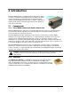
2 Introduction The Pearl OEM Camera is a flexible platform designed to support a variety of infrared imaging applications. The camera provides several configurations for integration into new and existing systems. The Pearl OEM Camera product is suited for applications requiring high quality infrared imaging without the added cost of precision radiometry. 2.1 2.1.1 Components Pearl OEM Camera and Pearl Camera Core The Pearl OEM Camera is a fully enclosed camera with external connectors.
2.1.3 Electronics The Pearl electronics includes a three-board stack, which allows for the flexibility of the camera. Each of these boards has standard connector footprints to stack together in all board configuration options. Power Board The Power Board requires an input power of 9 to 24-Volts DC to produce the required internal voltage levels that drive the camera electronics. The RS232 and video output signals are routed through this board.
2.1.4 Lens Options The Pearl Camera Core and Pearl OEM Camera are delivered without optics. A standard c-mount is provided along with design information required to design and use customer supplied lenses 2.1.5 Mounting and Enclosure The Pearl OEM Camera includes an enclosure while the Camera Core does not. The camera core is suitable for applications where the camera will be mounted inside an existing enclosure. Mounting holes are provided on the bottom of the Detector Lens Mount or front plate.
2.3 Technical Data 2.3.1 Performance Image Update Rate: 30 Hz (standard); 7.5 Hz (export series) A/D Resolution: Detector: Sensitivity/NETD: 16 bit Uncooled Focal Plane Array Options - 320x240 (37.5 µm pitch) 0.108 °F @ 86 °F (0.06 °C @ 30 °C) 2.3.2 Environmental Operating Temperature: Storage Temperature: Relative Humidity: Weight (No Lens): Operating Position: 2.3.3 Interface OEM Camera TV Output (NTSC) Coaxial (BNC) Analog Output: Digital Output: Power & Analog Video Out: RS232: 2.3.
2.4 2.4.
Pearl Camera Core Dimensions Pearl User Manual Introduction 14
3 Connections The Pearl models have different connections for providing power, RS232 communications, and either digital or composite video images. In all cases, the cameras required a connection for the 9 to 24 Volt DC input power. Composite Video output is available through a BNC connector or the 4-plug connector. The RS232 Interface is through the 3-plug connector. The following sections describe the connectors in detail.
3.1.1 Video Connection The video connection on the Pearl OEM camera is made directly to the BNC Jack on the back panel. Either connect a video cable with the BNC-to-RCA adapter, which is provided in the Pearl OEM Camera Kits, or use a BNC cable to connect the Video-Out BNC Jack to a video input on a monitor. BNC Video Connector 3.1.2 Center Video Ring Video Ground RS232 Connection A three position receptacle is used for the RS232 connections for TXD, RXD, and Ground.
3.2 Camera Core For the standard Pearl Camera Core, the Power Board provides all external connections. There is one connector for power and video and a second connector for the RS232 interface. RS232/Data Connector Power and Video Connector Pearl Camera Core showing available connectors. 3.2.1 RS232 Connection A three position receptacle is used for the RS232 connections for TXD, RXD and Ground. The adapter supplied in the Pearl OEM Camera Kit has a RS232 connector on one end.
To ensure consistent document formatting, this page was intentionally left blank.
4 Camera Operation The Pearl OEM Camera was designed for applications requiring high quality imaging with continuous operation. The camera has an approximate design life of 10 years. Periodic automatic calibrations are performed to ensure the best image quality for the detector. Optionally, the camera can be controlled through an external interface for experimentation, setup, or configuration for a wide variety of infrared thermal imaging applications.
Basic operation of the Pearl OEM Camera products using the PCS is described in the Pearl Control Software Manual, available on the disc or flash drive included with your camera or on the Lumasense website at: www.lumasenseinc.com/EN/products/ir-detectors-and-cores.
5 Troubleshooting In the event that the Pearl products are not displaying a thermal video image on the display, the following section describes a procedure for identifying a problem. Follow this procedure to regain basic imaging functions. Once the image is displaying properly, continue to modify the operating settings to optimize the operation for your application. 1. Check Electrical Connections The first step is to verify the connections to the camera are made properly.
To ensure consistent document formatting, this page was intentionally left blank.
Index A Accessories 11 B Board Stack 10 C Calibration 19 Camera Core 14, 17 Camera Operation 19 Configurations 11, 15 Connections 15 D Detector 9 Digital Board 10 Dimensions 13 Pearl Camera Core 14 Pearl OEM Camera 13 Disposal 8 Drawings 13 E Electrical 12 Electrical Connections 21 Electronics 10 Enclosure 11 Environmental 12 External Connections 15 G General Information 5 I Interface 12 Interface Board 10 L Legend 5 Lens Options 11 Liability 6 Pearl User Manual LWIR Lens Kit 11 M Models 11 Mountin
V Video Connection 16, 17 W Warranty 6 Pearl User Manual Index 24
Appendix A: Drawings & Diagrams Pearl OEM Camera Lens Adapter and FPA BWD Detail Pearl OEM Camera: Electrical Interface Pearl User Manual Appendix A: Drawings & Diagrams 25
Pearl Camera Core Pearl Camera Cores 137xxx, 337xxx, and 325xxx Lens Adapter and FPA BWD Detail Pearl Camera Cores Camera Core Electrical Connections Pearl User Manual Appendix A: Drawings & Diagrams 26