
User manual
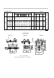

AUSFÜHRUNGEN Tabelle 1
Abmessungen
Stromklemmen
Typ
Spannungs-
abfall
Nennstrom
Form
nach
Bild
a1
a2
b1
b2
b3
c1
c2
e
h
Gewicht
[kg]
Anzahl
der
Klemmen
Sechskant-
schraube
Scheibe
Mutter
Span-
nungs-
klem-
men
1; 1,5; 2,5; 4;
6; 10; 15; 25;
A
90
28
20
-
-
8
-
78
-
0,13
2 x 1
M5 x 12
5,5
-
30; 40; 60; 100;
150; 180;
100
33
20
-
-
8
-
80
-
0,13
2 x 1
M8 x 16
8,5
-
Zwei
Zylinder
200; 250; 300;
145
55
30
15
-
10
10
105
30
0,60
2 x 1
M12 x 40
13
M12
schrau-
400; 500;
145
55
40
20
-
10
10
105
30
0,85
2 x 1
M16 x 45
17
M16
ben
B2
600; 800;
145
55
40
20
-
10
10
105
30
0,85
2 x 1
M16 x 45
17
M16
M5x8
60 mV
1000; 1200;
B
165
65
60
30
-
10
10
115
30
1,45
2 x 1
M20 x 50
21
M20
4 Schei-
1500; 2000;
165
65
90
21
48
10
10
115
30
2,00
2 x 2
M16 x 45
17
M16
ben 5,5
2500; 3000;
165
65
120
30
60
10
10
115
30
2,90
2 x 2
M20 x 50
21
M20
und
4000; 5000;
165
65
120
30
60
15
10
115
60
4,30
2 x 2
M20 x 60
21
M20
2 Feder-
6000; 8000;
C
175
70
154
25
52
25
15
125
130
10,50
2 x 3
M20 x 75
21
M20
scheiben
10000;
185
75
206
25
52
30
20
135
170
21,00
2 x 4
M20 x 85
21
M20
5.1
AUßENMAßE
Bauart A Bauart B Bauart C
Bild. 1 Montagemaße
1 - Isoliersockel (nur bis 25 A), 2 - Federring