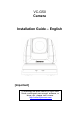
VC-G50 Camera Installation Guide – English [Important] To download the latest version of Quick Start Guide, multilingual user manual, software, or driver, etc., please visit Lumens http://www.Mylumens.
Table of Contents Copyright Information ....................................................................................... 3 Chapter 1 Safety Instructions .......................................................................... 4 Precautions .................................................................................................. 5 FCC Warning................................................................................................ 5 EN55022 (CE Radiation) Warning .....................
6.7 I would like to adjust the focal length................................................ 28 6.8 I would like to adjust the focus speed............................................... 28 6.9 I would like to set the image mode ................................................... 29 6.10 I would like to freeze images ............................................................ 29 6.11 I would like to rotate the image ......................................................... 29 6.
Copyright Information Copyrights © Lumens Digital Optics Inc. All rights reserved. Lumens is a trademark that is currently being registered by Lumens Digital Optics Inc. Copying, reproducing or transmitting this file is not allowed if a license is not provided by Lumens Digital Optics Inc. unless copying this file is for the purpose of backup after purchasing this product. In order to keep improving the product, Lumens Digital Optics Inc.
Chapter 1 Safety Instructions Always follow these safety instructions when setting up and using the Camera: 1. Use attachments only as recommended. 2. Use the type of power source indicated on the Camera. If you are not sure of the type of power available, consult your distributor or local electricity company for advice. 3. Always take the following precautions when handling the plug. Failure to do so may result in sparks or fire. Ensure the plug is free of dust before inserting it into a socket.
Precautions Warning: To reduce the risk of fire or electric shock, do not expose this appliance to rain or moisture. If Camera will not be used for an extended time, unplug it from the power socket. Note Risk of Electric Shock DO NOT OPEN Caution: To reduce the risk of electric shock, do not remove cover (or back). No user-serviceable parts inside. Refer servicing to licensed service personnel.
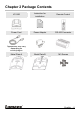
Chapter 2 Package Contents VC-G50 Instruction for installation Remote Control Power Cord Power Adapter RS-422 Connector Metal Plate B M3 Screws Appearance may vary depending on country/region Metal Plate A English - 6
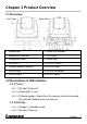
Chapter 3 Product Overview 3.1 Overview Front View Back View 1. Camera lens 2. Power LED indicator 3. Standby LED indicator 4. DVI output 5. Component output 6. Power input 7. IR SELECT 8. OUTPUT Switch 9. Camera Address Selectors 10. RS-232 output 11. RS-232 input 12. RS-422 connection 13. VIDEO output 14. 3G-SDI output 3.2 Description of LED indicator 3.2.1 Power: 3.2.1.1 No light: Power off 3.2.1.2 Green light: In use 3.2.1.
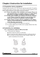
Chapter 4 Instruction for installation 4.1 Preparation before installation Installation and connection of VC-G50 Camera requires special skills. To install by yourself, please follow necessary steps, ensure steady and tight installation of the device, and pay attention to your safety to avoid any accident. 4.1.1 Ensure the safety of the installation environment. Please do not install the device on unstable ceiling or in a place where the device is in danger of falling to avoid any accident. 4.1.
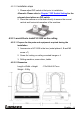
4.2.1.2 Installation steps 1. Please adjust DIP switch at first prior to installation. Please refer to Chapter 7 DIP Switch Setting for the relevant descriptions on DIP switch. 2. Place the camera on a flat desk directly to ensure the normal vertical and horizontal operation of the machine. 4.2.2 I would like to install VC-G50 on the ceiling 4.2.2.1 Prepare for the parts and equipment required during the installation 1. Accessories of VC-G50 in the box (metal plates A, B and M3 screw x 7) 2.
4.2.2.3 Size Diagram 1.
2.
3.
4.2.2.4 Precautions for installation 1. Before installation, please confirm the orientation of the machine relative to the object to be captured 2. It is recommended that the machine should be set at a distance of more than 1 meter away from the object to be captured. Please adjust for a best distance according to the magnification of the lens 1 meter↑ 3. The machine (including metal plates) is weighed at about 2.5 kg.
3. Lock the metal plate B on ceiling mounted hanger. ※Caution: (1) Please use the hanger that has obtained UL security approval (2) Please reserve the hole for the connecting wires of the camera 4.
4.2.2.6 How to remove 1. Remove the connecting wires from the camera 2. Uninstall the camera together with the ceiling, loosen the three screws that fix the metal plates A and B and push to the left to remove the machine 3.
4.3 Connecting the device 4.3.1 Image output 4.3.1.1 Connecting to a HDTV/computer monitor (DVI) DVI cable Monitor Or HDTV 4.3.1.
4.3.1.3 Connecting to a HDTV (3G-SDI) SDI Cable HDTV 4.3.1.
4.3.2 Controlling VCs with the computer 4.3.2.1 Connecting to one computer for connection between VCs (RS-232 in/out) With RS-232 in/out, at most 7 VCs can be connected. 4.3.2.2 Connecting to one computer for connection between VCs (RS-422) Please refer to 7.2 RS-422 connection for the RS-422 connection instructions. With RS-422, at most 7 VCs can be connected.
Chapter 5 Remote Control and Setting Menu 5.1 Functions of remote control The below functions are listed alphabetically.
5.2 Setting menu Press [Menu] on the remote control to enter the setting menu; the bold underlined values in the following table are defaults. st nd rd 1 Level 2 Level 3 Level Function Descriptions Major Adjustment Minor Items Items Values 1. Full Auto Mode 2. Shutter Pri 3. Manual Exposure mode setting 4. White Board Exposure_Co mp. On/Off Exposure_Co mp.
Manual Gain Manual Speed 1/180 1/150 1/120 1/120 1/100 1/100 1/90 1/75 1/60 1/50 1/30 1/25 1/15 1/12 1/8 1/6 1/4 1/3 1/2 1/2 1/1 1/1 1. 0dB 2. 2 dB 3. 4 dB 4. 6 dB 5. 8 dB 6. 10 dB 7. 12 dB 8. 14 dB 9. 16 dB 10. 18 dB 11. 20 dB 12. 22dB 13. 24dB 14. 26 dB 15. 28 dB 16.
Gain Limit 1/2000 1/1750 1/1500 1/1250 1/1000 1/1000 1/725 1/600 1/500 1/425 1/350 1/300 1/250 1/215 1/180 1/150 1/120 1/120 1/100 1/100 1/90 1/75 1/60 1/50 1/30 1/25 1/15 1/12 1/8 1/6 1/4 1/3 1/2 1/2 1/1 1/1 1. 2. 3. 4. 5. 6. 7. 8. 9. 10. 11. 12.
WDR White Balance Mode One Push Off 1 2 3 4 5 Auto Indoor Outdoor One Push WB ATW Sodium Lamp 3000K 4300K 5000K 6500K 8300K Wide Auto Set WDR Select the color temperature mode ENTER One push trigger Picture effect 1. Off 2. Neg 3. B&W Set the picture effect Sharpness 1~A~16 Adjust the sharpness of the image Trigger Picture 1. 2. 3. 4. 5. 6. 1. 2. 3. 4. 5. 6. 7. 8. 9. 10. 11. 12. 2D NR 3D NR 1. 2. 3. 4. 5. 6. 7. 1. 2. 3. 4. 5.
Image Mode Image Mode Load Pan Tilt Zoom 1. 2. 3. 4. 5. 6. 7. 1. 2. 3. 4. 5. 6. Mode1 Mode2 Mode3 Mode4 Mode5 Mode6 Custom Mode1 Mode2 Mode3 Mode4 Mode5 Mode6 The user may customize his/her desired image mode Adjustable when Image Mode is set to Custom. The user may load an Image Mode and apply it to Custom. Adjustable when Image Mode is set to Custom. Adjustable when Image Mode is set to Custom. Adjustable when Image Mode is set to Custom. Set skin tone, Adjustable when Image Mode is set to Custom.
Tilt Down Limit -30~0 Limit the downward angle D-Zoom Limit x1~x12 Limit the D-zoom multiple 1. 2. 3. 1. 2. 3. 4. Set the rotation speed of the cradle head when Preset is executed Preset Speed D-effect Mirror 150 deg/sec 250 deg/sec 350 deg/sec Off Mirror Flip Mirror + Flip AF Sensitivity 1. Low 2. Middle 3.
Factory Reset Status ON/Off Reset all configurations to factory default settings.
Chapter 6 Descriptions of Major Functions 6.1 I would like to switch to VC-G50 1. Press [Camera 1 ~ 3] on the remote control to select VC-G50. Camera 1 ~ 3 is selected with IR SELECT. 6.2 I would like to save the current lens position data 1. Press [Preset + ID] on the remote control to save the current position data. ID shall be a digit [0 ~ 9]. Use VISCA Command to save the position data to [0~127] 6.3 I would like to clear the saved position data 1.
6.6.2 Fine-tune image size 1. Press [Slow +] on the remote control to zoom in images. 2. Press [Slow -] on the remote control to zoom out images. 6.7 I would like to adjust the focal length 6.7.1 Auto tune 1. Press [AF] on the remote control to adjust automatically. 6.7.2 Manual focus 1. Press [MF] on the remote control to turn on the manual focus function. 2. Press Focus - [+] or Focus - [-] to adjust. 6.8 I would like to adjust the focus speed 6.8.
1. Press [MENU] to activate the setting menu. 2. Press [] or [] to select [Auto Focus]. 3. Press [ENTER] to activate. 4. Press [] or [] to select [AF Speed]. 5. Press [ENTER] to activate. 6. Press [] or [] to select [Normal/Fast]. 7. Press [MENU] to exit. 6.9 I would like to set the image mode 1. Press [Picture] on the remote control to switch [Off/Neg/B&W]. 6.10 I would like to freeze images 1. Press [Freeze] on the remote control to freeze the current image on the display. 6.
Chapter 7 DIP Switch Setting Please turn off the machine before changing DIP switch setting. 7.1 DIP SWITCH 7.1.1 OUTPUT Switch Output Mode Setting Output Mode 1920x1080/60p 1920x1080/50p 1920x1080/30p 1920x1080/25p 1920x1080/60i 1920x1080/50i 1280x720/60p 1280x720/50p 1280x720/30p 1280x720/25p 1920x1080/59.94p 1920x1080/59.94i 1920x1080/29.97p 1280x720/59.94p Setting 1280x720/29.
7.1.2 IR SELECT ID 1 Setting 2 3 7.1.3 Camera Address Selector Setting 0~7 8~9 Function Descriptions ID 0~7 Reserved 7.1.
7.2 RS-422 Connection 7.2.1 RS-422 Pin Description Pin NO. 1 2 3 4 5 6 7 8 9 Function RXD OUT RXD OUT + TXD OUT TXD OUT + GND RXD IN RXD IN + TXD IN TXD IN + 7.2.2 Use RS-422 Connection 1. Hold the two sides of RS-422 connector and pull out in the direction shown by the arrow in the figure below 2. Peel off a section of copper wire (AWG Nos.
3. Insert the wired RS-422 connector back to the camera. Now the connection is completed When RS-422 connection is being used, do not use RS-232C connection.
Chapter 8 Troubleshooting This chapter describes problems you may encounter while using VC-G50. If you have questions, please refer to related chapters and follow all the suggested solutions. If the problem still occurred, please contact your distributor or the service center. No. 1. 2. 3. 4. 5. 6.
7. The device cannot be controlled with RS-232/RS422 2. Make sure the connection is correct (RS-232/422 Input). 3. Make sure System Switch DIP1 and DIP3 are correct. 1. Make sure the connection is correct (RS-232/422 Input). 2. Make sure System Switch DIP1 and DIP3 are correct.