Lum/nex ® Luminex 100™ User Manual Version 1.
© LUMINEX CORPORATION, 1998 - 2004. All rights reserved. No part of this publication may be reproduced, transmitted, transcribed, or translated into any language or computer language, in any form or by any means without prior express, written consent of: LUMINEX CORPORATION 12212 Technology Boulevard Austin, Texas 78727-6115 U.S.A. Voice: (512) 219-8020 Fax: (512) 219-5195 Technical Support U.S.
End-User License Agreement (EULA) for Luminex® Software This Luminex End-User License Agreement (“EULA”) is a legal agreement between you (either an individual or a single entity, also referred herein as “you”) the end-user and Luminex Corporation (“Luminex”) regarding the use of the Luminex software product identified above, which includes computer software and online or electronic documentation and may include associated media and printed materials (if any) (“SOFTWARE PRODUCT” or “SOFTWARE”).
be accessed through use of the SOFTWARE PRODUCT is the property of the respective content owner and may be protected by applicable copyright or other intellectual property laws and treaties. This EULA grants you no rights to use such content. 5. EXPORT RESTRICTIONS. You agree that you will not export or re-export the SOFTWARE PRODUCT to any country, person, entity, or end-user subject to U.S.A. export restrictions.
Contents Introduction 1-1 Principle of Operation . . . . . . . . . . . . . . . . . . . . . . . . . . . . . . . . . . . 1-1 Basic Concepts . . . . . . . . . . . . . . . . . . . . . . . . . . . . . . . . . . . . . . . . 1-2 Fluidics . . . . . . . . . . . . . . . . . . . . . . . . . . . . . . . . . . . . . . . . . . . 1-2 Excitation . . . . . . . . . . . . . . . . . . . . . . . . . . . . . . . . . . . . . . . . . 1-3 xMAP Microspheres . . . . . . . . . . . . . . . . . . . . . . . . . . . . . . . . .
Luminex 100 User Manual Version 1.7 xMAP Technology Electronics . . . . . . . . . . . . . . . . . . . . . . . . . . . . . . . . . . . . . . . . 3-4 Recommended Equipment . . . . . . . . . . . . . . . . . . . . . . . . . . . . . . . 3-4 Printer. . . . . . . . . . . . . . . . . . . . . . . . . . . . . . . . . . . . . . . . . . . . 3-4 Uninterruptible power supply (UPS) . . . . . . . . . . . . . . . . . . . . 3-4 Surge Protector. . . . . . . . . . . . . . . . . . . . . . . . . . . . . . . . . . . . .
xMAP Technology Contents File . . . . . . . . . . . . . . . . . . . . . . . . . . . . . . . . . . . . . . . . . . 6-10 Edit . . . . . . . . . . . . . . . . . . . . . . . . . . . . . . . . . . . . . . . . . . 6-11 Analyzer . . . . . . . . . . . . . . . . . . . . . . . . . . . . . . . . . . . . . . 6-11 Sample . . . . . . . . . . . . . . . . . . . . . . . . . . . . . . . . . . . . . . . 6-11 Tools. . . . . . . . . . . . . . . . . . . . . . . . . . . . . . . . . . . . . . . . . 6-11 View . . . . . . . . . .
Luminex 100 User Manual Version 1.7 Troubleshooting xMAP Technology 8-1 Power Supply Problems . . . . . . . . . . . . . . . . . . . . . . . . . . . . . . . . . 8-2 Communication . . . . . . . . . . . . . . . . . . . . . . . . . . . . . . . . . . . . . . . 8-2 Pressurization . . . . . . . . . . . . . . . . . . . . . . . . . . . . . . . . . . . . . . . . . 8-3 Fluid Leaks . . . . . . . . . . . . . . . . . . . . . . . . . . . . . . . . . . . . . . . . . . . 8-4 Sample Probe . . . . . . . . . . . . . . . .
xMAP Technology Contents Glossary A-1 Product Numbers B-1 Hardware . . . . . . . . . . . . . . . . . . . . . . . . . . . . . . . . . . . . . . . . . . . . Software. . . . . . . . . . . . . . . . . . . . . . . . . . . . . . . . . . . . . . . . . . . . . Reagents . . . . . . . . . . . . . . . . . . . . . . . . . . . . . . . . . . . . . . . . . . . . Training . . . . . . . . . . . . . . . . . . . . . . . . . . . . . . . . . . . . . . . . . . . . . Luminex Sheath Delivery System C-1 Overview . . . . .
Luminex 100 User Manual Version 1.7 vi xMAP Technology PN 89-00002-00-063 Rev.
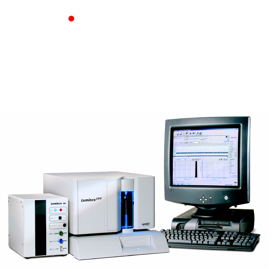
1 Introduction The Luminex® 100 system is a compact analysis unit consisting of a Luminex 100 analyzer, the Luminex XY Platform (Luminex XYP™), a PC, Luminex software, and reagents. The Luminex 100 analyzer integrates optics, fluidics, and advanced signal processing in a 17 inch by 20 inch footprint. The Luminex XYP provides efficient handling of 96-well microtiter plates. The PC uses Luminex software to control the analyzer.
xMAP Technology Luminex 100 User Manual Version 1.7 signature. In addition, the Luminex 100 analyzer scans each microsphere for the presence of a reporter fluorescence that quantifies the assay at the microsphere’s surface. The Luminex XYP works with 96-well plates that are no thicker than 0.75 inches. If you are not using the heater block, any brand of microtiter plate that meets this size requirement will work.
xMAP Technology Introduction Excitation The excitation system in the Luminex 100 analyzer uses two solidstate lasers. A reporter laser excites fluorescent molecules bound to biological reactants at the microsphere surface, and a classification laser excites fluorochromes embedded in the microsphere. The lasers illuminate the xMAP microspheres as they flow single-file through the cuvette.
Luminex 100 User Manual Version 1.7 xMAP Technology Fluorescence Compensation Fluorescent spillover occurs when an emission spectrum overlaps other emission criteria; therefore, selective filtering cannot occur. In most analyzers, emission spillover is corrected using a technique called compensation. Compensation involves subtraction of emission percentage from another emission signal.
xMAP Technology Introduction from the main menu bar, from the toolbar, and from menus that appear when you right-click an area of the screen. Technical Assistance You can find answers to frequently asked questions (FAQs) on our website: http://luminexcorp.custhelp.com. Technical assistance is available to users in the U.S. and Canada by calling toll free 1-877-785-BEAD (1-877-785-2323) between the hours of 7:00 a.m. and 7:00 p.m. Central Time, Monday through Friday. Users outside of the U.S.
Luminex 100 User Manual Version 1.7 1-6 xMAP Technology PN 89-00002-00-063 Rev.
2 Safety Your safety is important. Please do not perform procedures on your Luminex 100 system that are not specifically contained in this manual, unless you are directed to do so by Luminex Technical Support. This chapter discusses the following safety topics • Intended Use • Symbols • Safety Precautions Intended Use The Luminex 100 analyzer is designed for a wide range of indoor laboratory testing applications measuring biomolecular reactions on the surfaces of xMAP microspheres.
xMAP Technology Luminex 100 User Manual Version 1.7 Symbol Warnings and Notes Description 4 Off 5 Warning (see manual). 6 Warning (see manual). 7 Warning (see manual). 8 Warning (see manual). 9 Warning (see manual). 10 Warning (refer to manual) Informational notes and warnings may appear in this manual. Note: A note provides general helpful information. No safety or performance issues are involved.
xMAP Technology Safety with the specific safety advisories below, in addition to adhering to standard laboratory safety practices. The protection provided by the equipment may be impaired or the warranty voided if the equipment is used in a manner not specified by Luminex Corporation. Electrical The Luminex 100 analyzer and Luminex XYP must be connected to approved power sources. Do not perform any maintenance or cleaning of the system’s electrical components (except for the fuses).
Luminex 100 User Manual Version 1.7 xMAP Technology This label appears on the back of the Luminex 100 analyzer and the Luminex XYP. Figure 2-3. European Safety Requirements Label The Luminex 100 analyzer complies with European Union (EU) safety requirements and, therefore, may be marketed in the Europe Single Market. One of the following voltage labels displays on the back of the Luminex 100 analyzer, depending if the instrument uses a Coherent or Uniphase laser: Figure 2-4.
xMAP Technology Safety This voltage label displays on the back of the Luminex XYP: Figure 2-6. Luminex XYP Voltage Label Fluidics Warning: If the system is used to test biological samples, use your standard laboratory safety practices when handling system waste. The Luminex 100 analyzer contains fluidics. In the event of a fluid leak, turn off all power to the system and disconnect all power cords.
Luminex 100 User Manual Version 1.7 xMAP Technology This label appears on the back panel of the Luminex 100 analyzer: Figure 2-8. Laser Caution Label Do not remove the analyzer cover. When performing routine maintenance, ensure that power to the analyzer is OFF and the power cord is disconnected. All laser apertures in the analyzer are contained within a protective housing. This label appears on the optics cover within the Luminex 100 analyzer. Figure 2-9.
xMAP Technology Safety Figure 2-10. Avoid Exposure Label Caution: Use of controls or adjustments or performance of procedures other than those specified herein may result in hazardous radiation exposure. Caution: To avoid exposure to hazardous radiation, only perform procedures and adjustments as specified in this manual. Mechanical Warning: During operation, this system contains exposed, moving parts. Risk of personal injury is present. Observe all warnings and cautions.
Luminex 100 User Manual Version 1.7 xMAP Technology Heat Warning: The heater plate of the Luminex XYP may be hot and could cause personal injury if touched. Do not touch the heater plate. Blue Indicator Light 2-8 The blue light above the sample arm simply indicates the on/off status of the instrument, and is harmless. The blue light emitting diode (LED) does not emit light in the UV spectrum. PN 89-00002-00-063 Rev.
3 System Overview Hardware The Luminex 100 Version 1.7 system includes a Luminex 100 Version 1.7 analyzer, the Luminex XYP, and a PC. The Luminex 100 analyzer includes the following hardware: • • • • • Luminex 100 analyzer Sample tube holders (1.5 mL and 1.
xMAP Technology Luminex 100 User Manual Version 1.7 In addition, you can purchase the optional Luminex Sheath Delivery system (Luminex SD). xMAP Reagents Software • • • xMAP classification calibration microspheres (CAL1) xMAP reporter calibration microspheres (CAL2) Sheath fluid Luminex Data Collector software provides complete control of the Luminex 100 analyzer and performs real-time digital analysis of assays. The Luminex 100 system is preloaded with the Luminex software.
xMAP Technology Laser System Overview • • Fluidics • • • • Electronics • Reporter laser: 532 nm, nominal output 10-16.5 mW, maximum 500 mW, frequency-doubled diode; mode of operation mW, continuous wave (CW) Classification laser: 635 nm, nominal output 9.
xMAP Technology Luminex 100 User Manual Version 1.7 Luminex XYP Specifications General • • • • • • • • • Operating temperature: 15°C to 30°C (59°F to 86°F) Humidity: 20% to 80%, noncondensing Altitude: designed to operate at 2400 m (7874 ft.) above mean sea level or below. Physical dimensions: 44 cm (17.25 in) W x 61 cm (24 in) D x 8 cm (3 in) H Weight: 14.5 kg (32 lbs) UL installation category: UL Installation Category II, as defined in Annex J of UL 3101-1.
xMAP Technology System Overview Luminex 100 Analyzer Overview Electronic The Luminex 100 analyzer consists of three subsystems: electronic, fluidic and optical. The following section describes the useraccessible components of each subsystem. Chapter 7, "Maintenance and Cleaning", describes routine maintenance for each of these components. Power input module: Houses the analyzer on/off switch and fuses. P1 communications port (DB9): Connects the Luminex 100 analyzer to the computer.
xMAP Technology Luminex 100 User Manual Version 1.7 Fluidic Sample Arm: Transports the sample from the sample plate to the cuvette. Upon operation, the carriage drops automatically to the sample plate for sample retrieval. Sample Probe: Acquires sample from the sample plate. Cheminert® fitting: Holds the sample probe in place. Use the wheel to adjust the sample probe height. Warning: During operation, this system contains exposed, moving parts which can cause puncture wounds.
xMAP Technology System Overview Left Door, Access to Service Panel Center Door, Access to Syringe Figure 3-3. Front View of Luminex 100 Analyzer Showing Access Doors Air filter and access door: Cleans the air used to pressurize sheath fluid. This filter is enclosed behind an access door located on the back of the Luminex 100 analyzer. Figure 3-4. Air Filter on Rear of Instrument PN 89-00002-00-063 Rev.
xMAP Technology Luminex 100 User Manual Version 1.7 Syringe: Delivers sample from the sample plate to the cuvette. It is located in the compartment behind the center door. Syringe Seal Syringe Figure 3-5. Syringe Sheath filter: Removes particles greater than 10 microns in diameter from the sheath fluid. It is located behind the left access door. Sheath Filter Assembly Figure 3-6. Sheath Filter Assembly Air, waste fluid, and sheath fluid connectors: Connect to the sheath and waste fluid containers.
xMAP Technology System Overview Sheath Fluid Connector (Blue) Air Connector (Green) Waste Connector (Orange) Figure 3-7. Left Side of Analyzer - Air and Fluid Connectors Sheath fluid container (not shown): Holds sheath fluid. For proper operation, place the container at the same level as the analyzer. Do not place the container on top of the Luminex 100 analyzer. The sheath fluid level should be below the air inlet connection and above the sheath outlet connection.
Luminex 100 User Manual Version 1.7 Luminex XYP Instrument Overview xMAP Technology The Luminex XYP is a self-contained system. There is one access door that contains a plate holder and a reservoir. A heater plate can be placed in the plate holder. Reservoir You can use 70% isopropanol or 70% ethanol, deionized water, and 10%-20% bleach solution in the reservoir for Luminex 100 analyzer cleaning and maintenance procedures. Heater Block Use the heater block as required by your assay procedures.
4 Installation Luminex 100 System Installation Note: The Luminex 100 System is too heavy for one person to lift alone. Two people should unpack and lift the system to the workbench. Ensure that the facility complies with all system and safety requirements. If you are using the optional Luminex SD, install it after completely installing the Luminex 100 analyzer and the Luminex XYP. See the Luminex Sheath Delivery System appendix for instructions. To set up and start up the Luminex 100 system: 1.
xMAP Technology Luminex 100 User Manual Version 1.7 6. Replace the short sample probe with the long sample probe as follows: Unsnap the light housing above the probe. Loosen the Cheminert fitting that holds the sample probe in place. Gently grasp the probe and push up. Remove the sample probe out of the top of the sample arm. Push the long sample probe into the top of the sample arm, and tighten the Cheminert fitting. 7. Install the alignment guide by screwing it into the Luminex XYP as shown below.
xMAP Technology Luminex 100 Software Setup Installation After performing the Luminex 100 system assembly, ensure that the proper interface between the analyzer and PC is in place. To set up the software: 1. Turn on the Luminex 100 analyzer, then turn on the PC. The Luminex software launches automatically. 2. Click Yes to accept the End-User License Agreement. If the system does not prompt you to accept this agreement, read the agreement shown after the title page of this manual.
xMAP Technology Luminex 100 User Manual Version 1.7 Adjusting the Sample Probe Height Note: Adjusting the sample probe vertical height is critical. You must adjust the Sample Probe vertical height each time you install a Sample Probe, change the type or style of microtiter plate, or move the instrument. Thumb Wheel Height Adjustment Locking Screw Figure 4-4. Sample Probe Height Adjustment Tools To adjust the Sample Probe’s vertical height: 1.
xMAP Technology Installation 5. Place the 96-well microtiter plate on the Luminex XYP with position A1 in the top left corner and click Retract to retract the plate. 6. Use the 3/32 inch hexagonal allen wrench to loosen the height adjustment locking screw. See the photo on page 4-4. 7. Click Options on the toolbar. 8. Click Setup XY, then click Setup. This dialog box appears: 9. Click Test to lower the sample probe into well A1. 10.
xMAP Technology Luminex 100 User Manual Version 1.7 Installing Software and Firmware The Luminex 100 system arrives preloaded with the Data Collector software. It is possible that you may need to reload the software at some time. To reinstall the software: 1. Backup log files. Copy your template directory and the file named calibrationlog.mdb to a backup location. These files may be found in the Luminex setup directory. 2.
5 System Startup This chapter describes how to start up your system. The topics included are: • • • Luminex Main Window Luminex Main Window - a tour of the Luminex Main window Setup - describes how to set up the system Calibration - describes how to calibrate the instrument, add new lots of calibration microspheres, how to print calibration reports. Use the Luminex software to start the system.
Luminex 100 User Manual Version 1.7 xMAP Technology The Luminex Main window has six components: Title bar, Menu bar, Tool bar, Startup display, Status bar, and System monitor. The Title bar shows the name of the software, and changes depending on what section of the software you are using. The Menu bar contains commands to set up the Luminex 100 analyzer and perform data acquisition. See Chapter 6 for more detail.
xMAP Technology System Startup To add a new lot of xMAP classification calibration microspheres: 1. Click Calibrate. The Start Calibration dialog box opens. Figure 5-2. Start Calibration Dialog Box 2. Click New in the Classification Channel box. The Add New Classification Calibrator dialog box opens. Figure 5-3. Add New Classification Calibrator Dialog Box 3. Enter the information into the dialog box, using the values on the Certificate of Quality that came with your xMAP calibration microspheres.
Luminex 100 User Manual Version 1.7 Add New Reporter Channel Calibration Lots xMAP Technology Before you perform initial calibration for the analyzer, and whenever you receive a new supply of xMAP Calibration microspheres, enter the product and lot numbers and the calibration target values. To add a new lot of xMAP reporter calibration microspheres: 1. Click Calibrate. The Start Calibration dialog box opens. Figure 5-4. Start Calibration Dialog Box 2. Click New in the reporter channel area.
xMAP Technology Calibrate the Luminex 100 Analyzer System Startup In addition to calibrating the analyzer after installation, you can enhance optimal performance by calibrating the instrument daily as part of your startup routine and whenever the d Cal Temp temperature shown on the system monitor panel indicates a change of more than 3 degrees Celsius (°C). To calibrate the Luminex 100 analyzer: 1. Turn on the Luminex 100 analyzer.
xMAP Technology Luminex 100 User Manual Version 1.7 7. Fill the reservoir with a solution of 70% isopropanol or 70% ethanol. Click Retract on the toolbar to retract the plate holder. 8. Click Alcohol Flush, then click OK. The alcohol flush removes air from the fluidics. This takes about 5 minutes. 9. Click Calibrate on the main screen. The Start Calibration dialog box opens. Figure 5-7. Start Calibration Dialog Box 10. Enter your name in the Operator text box. 11.
xMAP Technology System Startup “Calibration Succeeded” message appears. The settings and any comment you enter are logged into the calibration report. 14. Click OK in the confirmation dialog box. The Calibration dialog box opens again. 15. Select Reporter and click Start. The progress bar shows you the calibration progress. Calibration should take less than two minutes. If the status in the system monitor changes to “Sample Empty” before calibration completes, a “Calibration Failed” message appears.
xMAP Technology Luminex 100 User Manual Version 1.7 3. Check the box in front of the report type you want. You can check both boxes to see both kinds of calibration report. 4. Click OK to print the calibration report, or Preview to see the report on your screen. Figure 5-10 shows an example of a calibration log. Figure 5-11 shows an example of calibration detail report. Figure 5-10. Calibration Log The calibration log shows gain values associated with each calibration.
xMAP Technology System Startup Figure 5-11. Luminex Calibration Detail Report The calibration detail report is often used by Luminex field service personnel when performing system maintenance. The report shows system temperature, Voltage, and pressure readings. Analyzer menu commands Use the Analyzer commands to prepare the Luminex 100 analyzer for sample acquisition, analysis, and shut down. On the Analyzer menu, choose the command you want to perform.
Luminex 100 User Manual Version 1.7 xMAP Technology Prime: Removes air pockets from the fluidic pathways. Use this operation after system installation and following replacement of the sheath fluid. Sheath fluid flows freely for several seconds followed by a fill-and-purge action by the syringe. Repeat until the waste line outside the instrument appears free of all significant air pockets. Alcohol flush: Removes air bubbles from the walls of the cuvette.
6 Data Acquisition The Luminex 100 analyzer uses Luminex Data Collector software to acquire data. This chapter describes the following topics: • • • • • • Options User tab Options Sessions Templates Multiplex Acquisition Data Collection Reports Before you can acquire data, you must set up some of the different options available. Click Options on the toolbar to open the Options dialog box. The Options dialog box has these tabs: User, Acquisition, Advanced, Setup XY, and Info.
xMAP Technology Luminex 100 User Manual Version 1.7 Sound effects: Enables sounds during system operation. Clear recent file list: Removes the list of recent files from the File menu. Do this each time you want to clear the list of recent files. Show project settings dialog on new session: Opens the project settings dialog box when you start a new session. You can also click Settings on the toolbar to open the settings dialog box.
xMAP Technology Acquisition tab Data Acquisition On this tab you can select the default folder for your session files. If you want a folder other than the one shown, click Browse and select a different folder. Figure 6-3. Options Dialog Box - Acquisition Tab Advanced tab Use the Advanced Tab to set properties in the Luminex Data Collector software. You can select multiple commands in this tab. Figure 6-4. Options Dialog Box - Advanced Tab Show Dot Plot.
Luminex 100 User Manual Version 1.7 xMAP Technology Show APD Voltages. This is a Field Service option. Do not select this option unless directed by Technical Support Show Project Properties. This is a Field Service option. Do not select this option unless directed by Technical Support. View Calibration Detail. Shows the detail screen while calibrating the instrument. Allow FileMode. Enables use to replay previously run sessions. Enable Liquid Handler. This is a Field Service option.
xMAP Technology Warning: The heater plate is hot when in use and may cause personal injury. Do not touch the heater plate. Allow the heater block to cool after use before touching it. Data Acquisition To use the heater, check Enabled in the Heater area. Use the Set Point control to select a temperature between 35°C and 60°C (95°F to 140°F). To maintain heater temperature between sessions, check Hold Temperature between sessions checkbox.
xMAP Technology Luminex 100 User Manual Version 1.7 Create a Session Using Default Settings To create a session using default settings: 1. On the Luminex main window, click New Session. The Settings dialog box opens. The values shown in the General tab are recommended settings. Figure 6-7. Settings Dialog Box - General Tab 2. Enter a name for the session in the Description field. Enter your name in the Operator field. Modify other fields as necessary.
xMAP Technology Data Acquisition 2. Select the template that you want to use for this session and click OK. If the template already contains a beadmap (or MAP), the template defaults to that MAP. If you have not yet selected a beadmap, this Choose Bead Map dialog box opens: Figure 6-9. Choose Bead Map Dialog Box Select the MAP you want to use and click OK. The 100 Region, 50 Region, and 25 Region MAPs are the standard MAPs for multiple analyte data collection.
xMAP Technology Luminex 100 User Manual Version 1.7 Open and Add to an Existing Session To open an existing session and add to it: 1. Click Open on the toolbar. The Open an Existing Session dialog box opens. Figure 6-11. Open an Existing Session Dialog Box 2. Double-click the session folder that contains the session that you want to use. The session information displays in the session group box. Click OK. The Multiplex Acquisition window opens. Figure 6-12.
xMAP Technology Data Acquisition 3. Use the settings shown or modify them, then highlight the first vacant sample. 4. Click Start to collect the new data; it is added to the established session. Open an Existing Session and Save it as a New Session To open an existing session and save it as a new session: 1. Click Open on the toolbar. 2. Choose the session folder and click OK. The established session appears. 3. Click File on the main menu bar and select Save As, then rename your session.
xMAP Technology Luminex 100 User Manual Version 1.7 2. Make desired setting changes. See “Session Settings” on page 614. 3. Click Edit on the main menu bar and select Create Template. Supply the same name as the loaded template. 4. When prompted to overwrite an existing template, select Yes. 5. Close the session and select No when asked to save changes to the current session. Delete a Template To delete a template: 1. Click Tools on the main menu bar and select Manage Templates. 2.
xMAP Technology Data Acquisition Open. Opens an existing session Close Session. Closes the current session. Prompts you to save the session before closing. Save. Saves the current session. Save As. Saves the current session under a new name. Print. Opens the print dialog box. You have the option of printing a results table, calibration log, bar graph, histogram, and dot plot. Print Setup. Opens the Print Setup dialog box. Use the settings in this dialog box to choose printer options. Exit.
xMAP Technology Luminex 100 User Manual Version 1.7 Help Contents. Opens the online help. Search for Help On. Opens a searchable index for the online help. Luminex on the Web. Opens a web browser window and navigates to the Luminex website. About Luminex Data Collector. Provides information about the Data Collector software. Toolbar The toolbar gives easy access to important commands of the main menu. Each of the commands are listed in the previous section. Figure 6-14.
xMAP Technology Data Acquisition Clear All: Clears the screen of all data and graphs. This function deletes all associated files. A confirmation dialog displays when you click this button to make sure that you intend to delete the table, graphs, and the data files for the session. Autosize: Adjusts column widths to fit the data and header sizes. Statistic: This dropdown list offers a choice of statistic types displayed in the table. Changing the statistic type does not affect collected or recorded data.
xMAP Technology Luminex 100 User Manual Version 1.7 Right-Click Menu Other commands appear on the right-click menu. To open this menu, right-click any sample cell. Figure 6-16. Right-Click Menu Load Data: Displays the data, including histogram and events information, of a selected (highlighted) sample. Start/Cancel: Begins or ends data acquisition. Delete Data: Deletes the data from a selected sample row. Copy: Copies selected information from the results table to the Windows clipboard.
xMAP Technology Data Acquisition We recommend using at least 100 events per microsphere set. This guarantees that each bead set selected acquires 100 events before completing sample acquisition. If each selected bead set does not acquire this number of events, you see a warning that not enough bead events were acquired. You can choose to keep the data or disregard it. Because of this option, when selecting bead sets on the Bead Set tab, you should choose only the bead sets present in your sample.
Luminex 100 User Manual Version 1.7 Bead Set tab xMAP Technology On the Bead Set tab you can select and name the appropriate microsphere sets. Select only microsphere sets that are present in your samples. Figure 6-18. Settings Dialog Box - Bead Set Tab Available: Lists available bead sets for the default beadmap (or MAP) selected in Options. See page 6-2 for more information. If the bead set you need is not on the Available list, click Options on the toolbar and select a different default MAP.
xMAP Technology Histogram Data Acquisition The histogram is located in the lower-left corner of the screen. The histogram provides a graphical display of the real-time data collection. An example of a histogram follows: Figure 6-19. Histogram Example The Y axis of the graph displays collected events. To autoscale the Y axis: Click the up-and-down arrow button shown just above the graph. To manually set the Y axis scale: 1. Right-click anywhere in the histogram to open the right-click menu.
xMAP Technology Luminex 100 User Manual Version 1.7 2. Click X axis, then click on the desired parameter name. If you select reporter 1 for the X axis parameter, the histogram displays reporter-generated intensity data. The central collected wavelength is 575 nm. With classification 1 or classification 2, peaks are based on the emission wavelengths of the classification dyes inside the microspheres; the central collected wavelengths are 658 nm and 712 nm, respectively.
xMAP Technology Data Acquisition Use the Show Bead options to set the histogram to show events for only one bead set, all gated events, or all events. There are five buttons to the upper right of the histogram: Auto scale: Automatically adjusts the maximum number of events shown on the Y axis. Click during acquisition to readjust the Y axis scale. Zoom: Enlarges a specific area on the histogram. Use the cursor and left mouse button to adjust the graph’s range.
Luminex 100 User Manual Version 1.7 xMAP Technology for later assays or sessions. By increasing this voltage setting, you may gain sensitivity; however, you may also compromise range. Decreasing this value has the opposite effect. To return to the calibrated RP1 setting, click Edit on the main menu bar and select Reset to Calibrated Settings. We recommend that you use the calibrated RP1 value. Bar Graph/Dot Plot Display You can toggle between the bar graph and dot plot displays.
xMAP Technology Data Acquisition density is indicated by contrasting colors. A decaying dot plot shows the 100 most recent events acquired by the Luminex 100 analyzer. Figure 6-26. Dot Plot Display In the upper right corner of the frame, four buttons let you control the display: Count/Result: Switches the display between count and result. This is either a count of the number of events collected for the bead ID, or an RP1 intensity result. The result is the median value for the events.
xMAP Technology Luminex 100 User Manual Version 1.7 the beads are hitting with respect to their region. The beads should hit within the white region shown. The colored dots show where the beads actually hit. Figure 6-27. Bead Details Box This display can be useful in troubleshooting problems. See the “Troubleshooting” chapter on page 8-1 for examples. If the beads do not register properly during sample analysis, recalibrate the Luminex 100 analyzer.
xMAP Technology Data Acquisition The message at the top reflects the current status of the Luminex 100 analyzer. Ready: Indicates that the Luminex 100 analyzer is ready to collect data. Pressure: Pressure normally displays during a routine pressure check at the beginning of each run. However, if the pressure message remains for more than 1.5 minutes, a lack of pressure exists in the system. Check for the following problems: • • • • Low sheath fluid Loose hose connections Loose cap on sheath fluid bottle.
xMAP Technology Luminex 100 User Manual Version 1.7 The system monitor section also shows information about temperature, pressure, voltage, and events. Air pressure generally runs a little higher than sheath pressure. It is normal to see a drop in pressure if several minutes elapse between sample runs. Information in the calibration box of the systems monitor, which appears when no session is open, is shown for the last successful calibration.
xMAP Technology Data Acquisition 5. In the results table of the new session, highlight the sample where you want to begin collecting data. 6. Click Start. You can see the progress of data collection on the histogram and the bar graph. Make sure that the Single box remains unchecked for continued sample acquisition. 7. After the analyzer finishes collecting data, select Save on the File menu. The analyzer saves your data in the session folder you selected when you created the session.
xMAP Technology Luminex 100 User Manual Version 1.7 9. Remove the microtiter plate from the plate holder. 10. Click Retract from the toolbar to retract the plate holder. Run a Range of Samples You can run a specific range of samples, as demonstrated in the highlighted samples shown below. 1 2 3 4 5 6 7 8 9 10 11 12 A B C D E F G H Figure 6-31. Sample Plate with Row of Samples To run a range of samples on a plate, follow these steps: 1. Create the session for this run. 2.
xMAP Technology Data Acquisition 9. Remove the microtiter plate from the plate holder. 10. Click Retract from the toolbar to retract the plate holder. Run a Single Sample To run a single sample: 1. Click Eject from the toolbar to eject the plate holder. 2. Place a 96-well microtiter plate on the plate holder. 3. Click Retract from the toolbar to retract the plate holder. 4. On the results table part of the acquisition screen, select the sample that you want to read. 5.
xMAP Technology Luminex 100 User Manual Version 1.7 To interrupt sample acquisition between sample runs: 1. Click Cancel. Sampling stops after you click Cancel. 2. Click OK to continue acquiring the next sample. Reports You can print the results table or histogram from any session. To print reports: Note: The analyzer does not support printing with the Windows NT operating system. 1. Load the desired data. 2. Click File on the main menu bar and select Print. The Print dialog box opens.
xMAP Technology Data Acquisition 6. In the Manufacturers List, click Generic. In Printers list, click Generic/Text Only. 7. Click OK throughout the rest of the windows. 8. You can now open report pages in Notepad, then print them to this printer. PN 89-00002-00-063 Rev.
Luminex 100 User Manual Version 1.7 6 - 30 xMAP Technology PN 89-00002-00-063 Rev.
7 Maintenance and Cleaning Warning: When analyzing potentially infectious biological samples on the Luminex 100 analyzer, follow proper biosafety procedures. These safety precautions should also be taken when cleaning or maintaining the Luminex 100 analyzer. Proper maintenance and cleaning of the Luminex 100 analyzer should be performed in order to preserve the analyzer’s longevity and reliability.
xMAP Technology Luminex 100 User Manual Version 1.7 Note: There is NO sensor to warn you of low sheath fluid levels. Fill the sheath fluid container before the level reaches the sheath outlet line. There is NO indicator light to warn you of high waste volume. Empty the waste container each time you fill the sheath container. 3. While you are waiting for the analyzer and optics system to warm up - about 30 minutes - check the levels of sheath fluid and waste fluid.
xMAP Technology Maintenance and Cleaning the waste, remove air from the lines by clicking Prime until no more air shows in the lines. Check for Leaks Note: In the event of a leak or spill inside the analyzer, make sure the power to the system is off and that the power cord is disconnected from the wall source. Calibrate Sanitize Check for leaks on a weekly basis. Open all analyzer doors and visually inspect for leaks. If you see a leak or spill, contact Luminex Corporation. Users in the U.S.
xMAP Technology Luminex 100 User Manual Version 1.7 Clean Sample Probe Clean the sample probe on a monthly basis, or whenever you suspect that it may be clogged. 1. Remove the sample probe as follows: Unsnap the light housing located above the probe. Unscrew the Cheminert fitting that holds the sample probe in place. Gently grasp the probe and push up. Remove the sample probe out of the top of the sample arm. Warning: Be sure that the system is not operating when you remove the sample probe. 2.
xMAP Technology Maintenance and Cleaning 2. On the back of the Luminex 100 analyzer, remove the thumbscrew at the top of the air intake filter access door. 3. Pull the access door off of the Luminex 100 analyzer. 4. Pull the filter out from the unit, about three or four inches. 5. Grasp the tubing. Remove the filter with one hand, and hold the tubing with the other hand. 6. Connect a new filter to the tubing. 7. Put the filter inside the panel, then reattach the panel door. Figure 7-2.
xMAP Technology Luminex 100 User Manual Version 1.7 3. Replace the filter and replace the screen. 4. Plug in and turn on the Luminex XYP. Replace Syringe Seal Replace the syringe plunger seal every 6 months. 1. Turn off and unplug the Luminex 100 analyzer. 2. Open the center door on the front of the Luminex 100 analyzer. Warning: The syringe arm does not deactivate when changing the plunger; injury could result if the system is not unplugged. 3.
xMAP Technology Clean Luminex 100 Analyzer Ventilation Filter Maintenance and Cleaning Check the Luminex 100 analyzer ventilation filter every 6 months. Clean the filter only when soiled. 1. Turn off the Luminex 100 analyzer at the power switch. 2. Unplug the power cord from the wall source. 3. On the bottom of the unit on the left side, push the filter out toward the right side. 4. Grasp the filter and pull it out from underneath the Luminex 100 analyzer. 5.
xMAP Technology Luminex 100 User Manual Version 1.7 Change the Sheath Filter and Quick-disconnect O-rings Change the sheath quick-disconnect o-rings as necessary. 1. Turn off the Luminex 100 analyzer at the power switch. 2. Remove the quick-disconnect fitting that has the faulty o-ring. 3. Use a small flat-head screwdriver to remove the worn out o-ring. 4. Place the new o-ring over the tip of a pair of closed needle-nose pliers. 5.
xMAP Technology Maintenance and Cleaning Power Module Door Figure 7-6. Power Module Adjust Sample Probe Vertical Height Note: Adjusting the sample probe vertical height is critical. The vertical height determines how far the sample probe goes into the sample tube or sample well when aspirating a sample. It is set when the Luminex 100 analyzer is shipped.
xMAP Technology Luminex 100 User Manual Version 1.7 3. In a 96-well microtiter plate where overall height is no more than 0.75 inches, place the appropriate alignment tool in the plate. • For a standard plate with flat-bottomed wells, stack two of the larger (5.08 mm diameter) alignment disks in well A1. • For filter-bottom plates, stack three of the larger alignment disks into well A1. • For a half-volume plate with flat-bottomed wells, stack two of the smaller (3.
xMAP Technology Maintenance and Cleaning 11. Use a 3/32 inch hexagonal allen wrench to tighten the height adjustment locking screw. 12. Click Test to raise the sample probe, then click OK to close the dialog box. 13. Replace the clear plastic shield that covers the sample probe area. Adjusting the Sample Probe Horizontal Position Luminex aligns the sample probe on your Luminex 100 analyzer prior to shipping, but you may need to adjust the horizontal position after installing the Luminex XYP.
xMAP Technology Luminex 100 User Manual Version 1.7 Decontaminating the Luminex 100 Analyzer for Return Shipment Note: If you are returning the Luminex XYP instrument or the Luminex SD instrument, decontaminate accessible surfaces using 10% bleach. Technical Support will supply a Return Material Authorization (RMA) number if they direct you to return the analyzer to Luminex, and instruct you in returning the analyzer according to Luminex procedures. Decontaminate the unit before shipping.
Month(s): ________________________________________Year:_______________ Date/Initials: Wipe exterior surfaces Date/Initials: Date/Initials: Replace syringe plunger seal, or syringe Check analyzer ventilation filter Comments: Replace fuses As required Replace sheath filter Date/Initials: Date/Initials: Date/Initials: Replace air intake filter, XYP (optional) Yearly Date/Initials: Replace air intake filter, analyzer Every six months Date/Initials: Clean sample probe Monthly Date/Initials:
8 Troubleshooting Troubleshooting procedures help users isolate, identify, and remedy problems with the Luminex 100 analyzer and Luminex XYP instrument. This chapter does not troubleshoot problems with the PC. For help with PC problems, please call Dell Technical Support at 800-624-9896. To troubleshoot a problem, start by selecting a general symptom Next, identify the possible problem and remedy it with one of the solutions listed.
xMAP Technology Luminex 100 User Manual Version 1.7 outside of the U.S. and Canada can call us at +1 512-381-4397 between the hours of 7:00 a.m. and 7:00 p.m. Central Time, Monday through Friday. You may send inquiries by email to support@luminexcorp.com. You can also read answers to common troubleshooting questions at http://luminexcorp.custhelp.com. Power Supply Problems Power supply problems often involve a blown fuse, faulty electronic component, or even something as simple as a disconnected cable.
xMAP Technology “Bad Link” error message Troubleshooting There is a bad link between the PC, analyzer, and/or XYP. Ensure that the instruments have power. Check the power cord and communication cable connections Shut down the PC and analyzer. Turn on the analyzer before turning on the PC. XY Platform microtiter plate connect error. Command timed out. Pressurization Symptom Pressurization Fails or Pressure too low. PN 89-00002-00-063 Rev. A The Machine Setup is using the wrong COM Port.
xMAP Technology Luminex 100 User Manual Version 1.7 Pressure too High Fluid Leaks Symptom Pressure too low The sheath bottle has an air leak. Disconnect the sheath and waste bottle connections from the analyzer. Run a Prime command. If pressure builds, remove and retighten the sheath fluid bottle cap, then reconnect fluid lines to the analyzer. If pressurization fails again, replace the sheath bottle. The sheath bottle is overfilled. Ensure that the sheath bottle is not filled above the fill line.
xMAP Technology Sample Probe Symptom Troubleshooting Problems with the sample probe can lead to fluid leaks and pressurization problems, as well as inhibit sample acquisition. Possible Problem Solution Sample probe leak The sample probe is clogged. Clean the sample probe. See page 7-4. Sample arm stuck in the up position The system isn’t properly pressurized. If a PRESSURIZATION error message displays, see Pressurization on page 8-3.
xMAP Technology Luminex 100 User Manual Version 1.7 Sample arm does not go down smoothly. The 96-well plate is incorrectly seated in the XYP. Adjust the 96-well plate. The 96-well plate is warped. Inspect the 96-well plate. Replace it if it is warped. The sample arm is misaligned. Readjust the sample arm horizontal alignment. The analyzer is misaligned with the XYP instrument. Reposition the Luminex 100 analyzer on top of the Luminex XYP instrument so that the holes match up correctly.
xMAP Technology Calibration of Classification Channel Does not complete Classification channel calibrates, but Reporter channel fails. PN 89-00002-00-063 Rev. A Troubleshooting The wrong wells are selected in the XY tab in the Luminex Data Collector software. On the Options Menu of the Luminex Data Collector software, click Options. When the Options window opens, click on the Setup XY tab.
xMAP Technology Luminex 100 User Manual Version 1.7 Zero events collected during calibration The calibration microspheres are not fully suspended. Vortex the calibration vials to resuspend the microspheres. Wrong calibration lot chosen in the Calibration Setup window. In the Main Window of the Luminex Data Collector software, click Calibrate. In the Start Calibration dialog box, make sure that the correct lot numbers are shown in the Reporter Channel menu.
xMAP Technology Slow or Unsuccessful Sample Acquisition PN 89-00002-00-063 Rev. A Troubleshooting The sheath or waste lines are not fully connected. Check to make sure all tubes are tightly connected The Calibration microspheres have expired. Replace old microspheres with a fresh lot. The calibration lot number selected in setup is incorrect. In the Main Window of the Luminex Data Collector software, click Calibrate.
xMAP Technology Luminex 100 User Manual Version 1.7 Bead Detail Irregularities The Acquisition volume is set too high. Set the acquisition volume to at least 25 µL less than the actual volume in your wells. This setting lets the analyzer acquire sample more efficiently with less chance of acquiring air. The xMAP microspheres are not fully suspended. Vortex or pipette your samples up and down to ensure that the beads are present in the solution. You are using photobleached microspheres.
xMAP Technology Troubleshooting Figure 8-2. Normal Histogram Symptom Possible Problem Solution Calibration microspheres classify too high You may be using photobleached calibration microspheres. Replace the microspheres with a fresh batch. To avoid photobleaching, protect your microspheres from light. xMAP microspheres hit toward the lower right of the region You may be using photobleached xMAP microspheres. Replace microspheres with a fresh batch.
xMAP Technology Luminex 100 User Manual Version 1.7 Microspheres appear as a long diagonal line The xMAP microspheres have agglutinated Add additional detergent to the assay buffer. For example, add .02% to 0.1% of Tween-20, Titron® X 100, or SDS. The solvent is incompatible. See the Technical Support website http:luminexcorp.custhelp.com for a list of incompatible solvents. If the solvent you are using is listed on the website, switch solvents. You are using incompatible sheath fluid.
xMAP Technology Troubleshooting “...an increased usage of power A warmup error occurred. to the green laser.” If the message appears following a warmup cancellation, turn off the analyzer and the PC. Restart them. Complete a full 30-minute warmup period and attempt calibration. If the message occurs more than once without warmup cancellation, contact Technical Support. “heater block temperature not in range. The heater block temperature is out of range.
xMAP Technology Luminex 100 User Manual Version 1.7 Cannot Create Folder: Check You used invalid characters when Make sure your file name doesn’t for Invalid Characters in Name creating a file name. contain any of the following characters: /:\*“?”<|> Printing Errors The results table does not print correctly Cannot view calibration log Verification The printer type is not compatible. Use compatible printer, or print the results in Excel from the Output.csv file. A printer driver error occurred.
xMAP Technology Troubleshooting the sample probe is properly aligned for use with the plate chosen for use. 7. Click Options on the toolbar. The options dialog box opens. 8. On the User tab, click Browse. Select the Calibrator beadmap then click OK. Click OK again to close the Settings dialog box. 9. Click New Session on the opening screen to open a new session. A Settings dialog box opens. 10.
Luminex 100 User Manual Version 1.7 8 - 16 xMAP Technology PN 89-00002-00-063 Rev.
9 Protocols Updates or additions to these protocols are posted on the Luminex website at http://luminexcorp.custhelp.com.
xMAP Technology Luminex 100 User Manual Version 1.7 Note: Failure to perform this procedure can result in decreased amounts of xMAP microspheres recovered in future sample aliquots. 3. Sonicate the vial in a water bath sonicator to disperse the microsphere pellet. 4. Vortex the vial immediately prior to dispensing. Larger 4 mL and 16 ml vials should be placed on a rotator for a minimum of 15 minutes for complete resuspension.
xMAP Technology Enumeration of xMAP Microsphere Suspensions Protocols Luminex xMAP microspheres are provided at standard concentrations. The xMAP microsphere yield after a coupling process may be less than the starting concentration due to loss during wash steps. The xMAP microsphere loss can vary according to operator technique, coupled reactant properties, and scale of coupling. It is not advisable to construct an assay without defining the concentration of the coupled microsphere suspension.
Luminex 100 User Manual Version 1.7 xMAP Microsphere Stability and Storage 9-4 xMAP Technology xMAP microspheres are light sensitive and should be protected from light during all stages of storage and usage. In addition, freezing conditions and organic solvents should be avoided. PN 89-00002-00-063 Rev.
xMAP Technology Protocols Two-Step Carbodiimide Coupling of Protein to xMAP Carboxylated Microspheres Introduction Use the protocols included here as a general starting point for developing assays. All assays should be optimized for your reagents in your specific application. You will discover the methods that give you the best results by starting with these guidelines and modifying them for your specific needs.
xMAP Technology Luminex 100 User Manual Version 1.7 Preparation 1. Allow all reagents to warm to room temperature. 2. Dilute the protein stock with COUPLING BUFFER to a concentration of 25 - 250 µg/ml and a volume of at least 500 µl (See Technical note 2). 3. Using an analytical balance, weigh approximately 10 mg of Sulfo-NHS into a tube. Repeat for EDC (See Technical note 1). Procedure xMAP Microsphere Activation. 1. Centrifuge the xMAP microsphere stock for 1 minute at 8,000 × g or higher. 2.
xMAP Technology Protocols 13. Add 500 µL of COUPLING BUFFER to the activated xMAP microspheres and vortex. Centrifuge the activated xMAP microspheres for 1 minute at 8,000 × g or higher. Aspirate the supernatant. 14. Repeat the previous step and go immediately to the protein coupling steps. Coupling, Blocking, and Storage. 1. To initiate the coupling reaction, add 500 µl of the protein preparation (protein stock in COUPLING BUFFER) to the activated xMAP microspheres; vortex. 2.
xMAP Technology Luminex 100 User Manual Version 1.7 One-Step Carbodiimide Coupling of Oligonucleotides to xMAP Carboxylated Microspheres Introduction These protocols are a general starting point for developing assays. All assays should be optimized for your reagents in your specific application. Methods that give you the best results start with these guidelines and are modified for your specific needs.
xMAP Technology Procedure Protocols 1. Centrifuge the xMAP microsphere stock for 1 minute at a minimum of 8,000 x g. 2. Disperse the pellet with sonication, and vortex the container for 20 seconds. 3. Dispense 5.0 × 10⁶ of the xMAP microspheres from the stock tube into a 1.5 ml microcentrifuge tube (See Technical note 2). 4. Microcentrifuge the xMAP microspheres at 8,000 × g or higher for 1 minute. 5. Remove the supernatant, being careful not to disturb the pellet. 6. Add 50 µl of 0.1 M MES (pH 4.5).
xMAP Technology Luminex 100 User Manual Version 1.7 Technical notes 1. Oligonucleotides must be synthesized with a 5’ or 3’ amino group. No Tris or Azide or other amine-containing buffers should be present during the coupling procedure. Preferably, the oligonucleotide should be resuspended in water following synthesis. If oligonucleotides were previously solubilized in an amine-containing buffer, then precipitation and resuspension into water is required. 2. This procedure can be scaled up or down. 3.
xMAP Technology Protocols • • REACTION BUFFER: Phosphate Buffered Saline (pH 7.3 ± 0.1), Bovine Serum Albumin (10 mg/ml) BLOCKING/STORAGE BUFFER: Phosphate Buffered Saline (pH 7.3 ± 0.1), Tween 20 (0.02% v/v), Bovine Serum Albumin (1 mg/ml), Sodium Azide (0.05% w/v) Preparation 1. Dilute the Biotin-conjugated molecule in REACTION BUFFER to a concentration of 4 - 4000 nM (See Technical note 1). Procedure 1. Centrifuge the Avidin-modified xMAP microsphere stock for 1 minute at 8,000 × g or higher. 2.
Luminex 100 User Manual Version 1.7 Technical notes xMAP Technology 1. The concentration of Biotin-conjugated molecules is provided as a guide for assay development. The concentration required for optimal reactivity must be determined empirically for each specific biotin-conjugated molecule. 2. The reaction volume can vary with the reagent volume. If the reagent is limited, perform the reaction in a proportionately low volume. 9 - 12 PN 89-00002-00-063 Rev.
A Glossary aggregated microspheres Two or more xMAP microspheres that have adhered together. Alexa 532 Fluorochrome used for reporter channel with Ex/Em=531/554. (product of Molecular Probes, Inc.) ambient temperature The temperature of the surrounding environment. analyte A substance that is detected through assay analysis. Each test or unique xMAP microsphere type will test for a specific analyte. assay A quantitative measurement of a particular compound.
xMAP Technology Luminex 100 User Manual Version 1.7 calibrators xMAP microspheres used to normalize the settings for the reporter channel, both classification channels, and the doublet discriminator channel for the Luminex 100 analyzer. carboxylated microspheres An xMAP microsphere set that has been chemically modified so that its surfaces are covered with carboxyl functional groups (COOH) that allow covalent biomolecule attachment. CL1 Refers to dyes embedded in the xMAP microsphere.
xMAP Technology emission spectrum emission spectrum Wavelength range that an excited fluorochrome emits when its electrons fall from a higher to a lower energy state. Expressed in nanometers (nm). event Occurs when the signal processor determines that a particle is being observed. Ex/Em A common way of reporting a molecule’s excitation and emission wavelengths (for example, Ex/Em = 488/520). excitation spectrum Wavelength range that excites a molecule’s electrons to a higher energy state.
xMAP Technology Luminex 100 User Manual Version 1.7 xMAP microsphere set Luminex multi-analyte microspheres containing a unique mixture of two distinctly-colored fluorochromes to distinguish them from other multi-analyte microspheres. laser Light Amplification by Stimulated Emission of Radiation (laser). This highly purified source of light is an efficient way to excite fluorochrome electrons.
xMAP Technology reporter reporter A molecule (or combination of molecules) with a specific range of excitation and emission wavelengths that are used to identify or quantify an analyte. Examples of acceptable reporters for the Luminex 100 analyzer are Phycoerythrin and Alexa 532. reporter channel (RP or RP1) A specific range of wavelengths that includes the emission wavelength of a designated reporter molecule.
Luminex 100 User Manual Version 1.7 A-6 xMAP Technology PN 89-00002-00-063 Rev.
B Product Numbers Note: These part numbers are subject to change without notification. Hardware PN 89-00002-00-063 Rev. A Air filter (accessed through back of analyzer) CN-0001-01 Air intake filter (on bottom of analyzer) CN-0002-01 Serial cable CN-0005-01 Computer (Dell® PC) CN-PC01-01 Fuses, 2 Amp CN-0019-01 Heater block for XYP CN-0017-01 Luminex 100 (Analyzer) with PC and monitor CN-L002-01 Luminex 100 User Manual, Version 1.
xMAP Technology Luminex 100 User Manual Version 1.
xMAP Technology xMAP development microspheres (carboxylated) 1, 4, and 16 mL L100-CDEV1-[size code of 01, 04, or 16] xMAP development microspheres (LumAvidin), 1 mL L100-LDEV1 xMAP carboxylated microspheres 1, 4, and 16 mL L100-C1[region number]-[size code of 01, 04, or 16] for example, to order 1 mL of region 34 microspheres, use product number L100-C134-01 xMAP (LumAvidin) microspheres, 1 mL L100-L1[region number]-[size code] for example, to order 1 mL of region 22 microspheres, use product number
Luminex 100 User Manual Version 1.7 B-4 xMAP Technology PN 89-00002-00-063 Rev.
C Luminex Sheath Delivery System Overview Use this appendix to install, use, and maintain the Luminex Sheath Delivery System (Luminex SD™). Specifications General • • • • • • • Power Intended Use PN 89-00002-00-063 Rev. A • • Ambient temperature: 15°C to 30°C (59° to 86°F) Humidity: 20% to 80%, noncondensing Altitude: designed to operate at up to 2400m (7874 feet) above mean sea level Physical dimensions: 20 cm (8 inches) W x 30 cm (11.75 inches) D x 24.75 cm (9.
xMAP Technology Luminex 100 User Manual Version 1.7 Hardware The Luminex SD system includes: • • • • • • • Luminex Sheath Delivery device Waste line tubing (orange fitting) Sheath fluid line (blue fitting) Air line (green fitting) Sheath fluid intake line (white fitting) Power cord Screwdriver 1. 2. 3. 4. 5. 6. 7. 1. Power and Fault Indicators 2. Prime Button 3. Regulator Adjust 4. Air In Connector (green) 5. Sheath Out Connector (blue) 6. Sheath In Connector (white) 7.
xMAP Technology Installation Luminex Sheath Delivery System To install the Luminex SD system: 1. Locate the sheath fluid and waste bottles that are connected to the Luminex 100 analyzer. Check that the sheath fluid bottle is filled to just below the air intake valve. 2. Verify that the Luminex 100 analyzer is turned on and start the Luminex Data Collector software. Perform the following tasks. 3. Calibrate the system. See “Calibration” on page 5-2. 4.
xMAP Technology Luminex 100 User Manual Version 1.7 receptacle is level with the Luminex 100 analyzer or no more than three feet below it. Note: Ensure that the sheath fluid box is at least three feet below the system, otherwise the Luminex SD system will overfill. • Connect the sheath fluid intake line (white fitting) to the Sheath In connector on the front of the Luminex SD system. • Connect the power cord to the back of the Luminex SD system and plug the other end into an approved outlet. 7.
xMAP Technology Luminex Sheath Delivery System until the sheath pressure displayed in the System Monitor reads the same as the sheath pressure you recorded in step 4. The system should stabilize at this sheath pressure. The air pressure should be the same as you recorded in step 4, within 0.1 psi. If the Prime cycle ends before you have completed the adjustment, select Prime again and continue to adjust the regulator. 11. Calibrate the system again.
Luminex 100 User Manual Version 1.7 xMAP Technology Regularly, as required. Replace the sheath fluid as required. Weekly. Visually inspect the Luminex SD system and its connections for leaks. If you see a leak, turn off the power to the Luminex SD system and contact Luminex Corporation. Monthly. Turn off the power to the Luminex SD system. Clean the exterior surfaces by wiping with mild germicidal detergent, followed by a 10%-20% bleach solution.
xMAP Technology Labels PN 89-00002-00-063 Rev. A Luminex Sheath Delivery System The following labels are attached to the back of the Luminex SD.
xMAP Technology PN 89-00002-00-063 Rev.
Index Numerics B 100 region bead map 6-2 25 region bead map 6-2 50 region bead map 6-2 back flush command 5-10 background 6-19 bad link 4-3, 6-23 bar graph buttons 6-21 printing 6-28 bead acquisition, rate 6-22 bead events 6-14 bead ID 6-20 bead map 6-2, 6-7 bead map, default 6-2 bead set 6-16 bead set tab 6-16 biohazard 2-2, 2-7, 7-1 blue light 2-8 busy 6-23 A access doors 3-6 Acquisition tab 6-3 additional equipment 3-4 uninterruptible power supply (UPS) 3-4 adjust sampling probe, vertical height 4-4
xMAP Technology Luminex 100 User Manual Version 1.
xMAP Technology histogram 6-17 buttons 6-19 changing X-axis 6-17 display 6-10 gating 6-18 printing 6-28 scaling Y-axis 6-17 Index Luminex Corporation, contact information 1-5, 7-3 Info tab 6-4 installation 4-1 intended use 2-1 intended use, Luminex SD C-1 Luminex Data Collector 3-2 Luminex SD 4-1 Luminex SD system, includes C-2 Luminex SD, alarms C-5 Luminex SD, installation C-3 Luminex SD, intended use C-1 Luminex SD, maintenance and cleaning C-5 Luminex SD, specifications C-1 Luminex SD, troubleshoo
Luminex 100 User Manual Version 1.
xMAP Technology Index spillover, fluorescent 1-4 standby 6-23 start 6-13, 6-14 startup procedure 7-1 status 6-22 status bar 6-10, 6-24 support 1-5, 8-1 syringe 3-8 access to 3-6 syringe cylinder product number B-2 syringe seal maintenance 7-6 product number B-2 system monitor 6-10, 6-22 W T X technical assistance 8-1 telephone number 8-1 temperature, on system monitor 6-22 template 6-6, 6-9 threshold 6-19 thumb wheel adjusting vertical height 4-4 title and main menu bars 6-10 toolbar 6-10, 6-12 total
Luminex 100 User Manual Version 1.7 Index-6 xMAP Technology PN 89-00002-00-063 Rev.