Luminex 100E™ User Manual
© LUMINEX® CORPORATION, 2004. All rights reserved. No part of this publication may be reproduced, transmitted, transcribed, or translated into any language or computer language, in any form or by any means without prior express, written consent of: LUMINEX CORPORATION 12212 Technology Boulevard Austin, Texas 78727-6115 U.S.A. Voice: (512) 219-8020 Fax: (512) 219-5195 Luminex 100ETM User Manual CN-M028-01 PN 89-00002-00-013 Rev.
Contents Introduction 1-1 About This Manual . . . . . . . . . . . . . . . . . . . . . . . . . . . . . . . . . . . . . 1-1 Intended Use . . . . . . . . . . . . . . . . . . . . . . . . . . . . . . . . . . . . . . . . . . 1-1 Customer Support . . . . . . . . . . . . . . . . . . . . . . . . . . . . . . . . . . . . . . 1-2 Safety 2-1 Symbols . . . . . . . . . . . . . . . . . . . . . . . . . . . . . . . . . . . . . . . . . . . . . . 2-1 Safety Precautions . . . . . . . . . . . . . . . . . . . . . . . . . . .
Luminex® 100E™ User Manual Version 1.0 xMAP Technology Maintenance and Cleaning 4-1 Overview . . . . . . . . . . . . . . . . . . . . . . . . . . . . . . . . . . . . . . . . . . . . Daily . . . . . . . . . . . . . . . . . . . . . . . . . . . . . . . . . . . . . . . . . . . . . . . . Before Running Samples . . . . . . . . . . . . . . . . . . . . . . . . . . . . . After Running Samples . . . . . . . . . . . . . . . . . . . . . . . . . . . . . . Monthly . . . . . . . . . . . . . . . . . . . . . . . . . . .
1 Introduction About This Manual Intended Use This manual introduces you to the Luminex® 100E™ analyzer. It explains the features of the Luminex 100E analyzer and provides instructions on installation and use of the analyzer. The Luminex 100E analyzer is designed as a component in a host system. This component is designed for a wide range of laboratory testing applications measuring biomolecular reactions on the surfaces of xMAP® and customer-specific microspheres. It is intended for indoor use only.
Luminex 100E User Manual Technical Support xMAP Technology You can contact Luminex Technical Support for questions or concerns regarding the Luminex 100E analyzer. Users in the U.S. and Canada may call 1-877-785-BEAD (-2323) between the hours of 7:00 a.m. and 7:00 p.m. Central Time, Monday through Friday for assistance. Users outside of the U.S. and Canada can contact us at + 1 512-381-4397 between the hours of 7:00 a.m. to 7:00 p.m. Central Time, Monday through Friday.
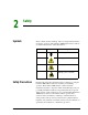
2 Safety Symbols These symbols describe warnings, cautions, and general information used in the operation of this Luminex 100E analyzer. These symbols are further defined under “Safety Precautions.” Number Safety Precautions PN 89-00002-00-013 Rev. D Symbol Description 1 Protective ground 2 Warning (refer to manual) 3 Warning (refer to manual) 4 Warning (refer to manual) Read the following safety information before setting up or using the Luminex 100E analyzer.
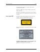
xMAP Technology Luminex 100E User Manual The following labels appear on the back panel of the Luminex 100E analyzer. Figure 1. Voltage Label Figure 2. FCC Label Note: This equipment has been tested and found to comply with the limits for a Class B digital device, pursuant to part 15 of the FCC Rules. These limits are designed to provide reasonable protection against harmful interference in a residential installation.
xMAP Technology Safety Do not perform any maintenance or cleaning of the electrical . components of this system. The Luminex 100E analyzer complies with European Union (EU) safety requirements. This analyzer contains fluidic components. In the event of a fluidic leak, disconnect the power. Contact Luminex Corporation for further information. Laser, Luminex 100E United States and international regulations require the following warnings to appear on the analyzer during operation and maintenance.
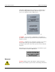
Luminex 100E User Manual xMAP Technology All Luminex 100E analyzer laser apertures are contained inside a protective housing within the analyzer. This label appears on the optics cover within the Luminex 100E analyzer. Figure 5. Laser Caution Label on Optics Cover CAUTION — Use of controls or adjustments or performance of procedures other than those specified herein may result in hazardous radiation exposure.
xMAP Technology Safety Warning: During operation, this analyzer contains moving parts that result in a pinch point hazard. Risk of personal injury is present. Keep hands and fingers away from the syringe arm. Biological Warning: All human/animal samples may contain hazardous infection agents.
xMAP Technology Luminex 100E User Manual Decontaminating the Luminex 100E Analyzer for Return Shipment Note: You are responsible for decontaminating the unit prior to shipment. Luminex Technical Support will provide a Return Material Authorization (RMA) number if they direct you to return the analyzer to Luminex; they will also instruct you in returning the analyzer according to Luminex procedures.
3 Luminex 100E Analyzer Overview Theory of Operation The Luminex 100E analyzer was specifically designed to be a component of a host system. Luminex 100E analyzer technology is based on flow cell fluorometry with Luminex-developed innovations. The fluidics and optics work together to enable simultaneous analysis of up to 25 analytes in a single test sample using the Luminex 25 beadmap. There are two fluidics paths in the Luminex 100E analyzer.
xMAP Technology Luminex 100E User Manual diode (APD) detectors measure the excitation emission intensities of the color coding classification dye mixtures inside the microspheres and a photomultiplier tube detects the excitation emission intensity of the reporter dye bound to the surface of the microspheres. High speed digital signal processors (DSP) and advanced computer algorithms provide analysis of the microspheres as they are processed through the Luminex 100E analyzer.
xMAP Technology Luminex Runtime (LXR) Luminex 100E Analyzer Overview Luminex Runtime (LXR) version 2.0 is a set of software components that provides simple, standardized mechanisms for programmable control of the Luminex 100E analyzer. Use the LXR Software Development Kit (SDK) version 2.0 or greater to write your own programs that analyze the results from the Luminex 100E analyzer. It includes sample test programs. Online documentation and other test programs are in the LXR Programmer’s Reference.
xMAP Technology Luminex 100E User Manual • • • • • • • • • Sensitivity Physical dimensions, excluding mounting brackets, connectors, and tubing, are: 31.1 cm (12.25 inches) W x 50 cm (19.7 inches) D x 29.2 cm (11.5 inches) H Weight: 21.8 kg (48.0 lbs.) Shipping and storage: The allowable shipping and storage temperature and humidity ranges are 0°C to +50°C and up to 80% noncondensing Underwriters Laboratories, Inc.
xMAP Technology Fluidics Electronics System Overview User-Accessible Components Power Input Connector Luminex 100E Analyzer Overview • • • • • Sheath flow specification rate: 90 µL/second ± 5 µL/second Cuvette: 200 micron square flow channel Sample injection rate: 1 µL/second ± .05 µL variable default Sample uptake volume: 20 - 200 µL Pressure connections to the unit should not exceed 10 PSI during normal operating conditions.
xMAP Technology Luminex 100E User Manual The power input connector type is a Amphenol JTP02RE-2221P(014), and it connects with Amphenol JT06RE-22-21S(014). Equivalent parts can be used. The Luminex 100E analyzer operates off of five separate dc voltage levels, including 24 volts, 15 volts, -15 volts, and 6 volts. The pinout follows below: • • • • • • • • • • • • • +15 -15 +24 +6 +15 Return +24 Return +6 Return Chassis ground 5.4 volts 5.4 Return 5.4 V (+) sense 5.
xMAP Technology Luminex 100E Analyzer Overview Supply voltage (V) Noise (mVpp) Maximum Current (Amps) +6.0 ±2% 60 1 + 5.4 220 10 +24.0 ±2% 240 2 +15.0 ±3% 150 1 -15.0 ±3% 150 0.5 The 24 volt power supply should not be capable of delivering, under any load condition including short circuit, 8 amps after one minute of operation. The 15 volt, negative 15 volt, and 6 volt, and 5.
xMAP Technology Luminex 100E User Manual The P1 Communications Port is a nine-pin DB female-style connector for communication between the P1 port and the host computing and control system. Table 1 lists the P1 communications port pinouts. Table 1: P1 Communications Port Pinout Pin Number P2 Synchronization Port (DB15-PIN) voltages Description Pin 1 None USB D- Pin 2 Maximum of 5.
xMAP Technology Luminex 100E Analyzer Overview Table 2 lists the P2 synchronization port pinouts. Table 2: P2 Synchronization Port Pinout Pin Number PN 89-00002-00-013 Rev. D voltages Description Pin 1 None Unused Pin 2 None Input 1 return Pin 3 Unloaded, maximum voltage of 5.
xMAP Technology Luminex 100E User Manual Air Filter The air filter is located on the front of the Luminex 100E analyzer behind the front panel. See “Air Filter” on page 4-4 for more information. For proper ventilation, do not obstruct the area in front and allow at least one inch (2.54 cm) of clearance around the Luminex 100E analyzer. Figure 9.
xMAP Technology Luminex 100E Analyzer Overview 1 2 3 1. Nonpressurized Sheath Fluid Connector (Blue) 2. Waste Fluid Connector (Orange) 3. Pressurized Sheath Fluid Connector (Green) Figure 10. Regulated Flow Sheath Supply Sample Input Tube The sample input tube provides the sample fluid interface between the sample probe from the host system to the Luminex 100E analyzer. This sample input tube aspirates sample. Figure 11. Sample Input Tube (Without Cap) Optical PN 89-00002-00-013 Rev.
xMAP Technology Luminex 100E User Manual Installing the Luminex 100E Analyzer into the Host System The Luminex 100E analyzer has three electrical and four fluid connectors that interface to the host system: • • • • • • • P1 Communications Port P2 Synchronization Port Power input connector Sample Input Tube Nonpressurized Sheath Fluid Connector Waste Fluid Connector Pressurized Sheath Fluid Connector To install the Luminex 100E analyzer into the host system: Note: Due to the weight, use two people to
Luminex 100E Analyzer Overview xMAP Technology NOTES: CLEARANCE FOR COOLING AND INTAKE/EXHAUST. 1. THE LUMINEX 100E IS A COMPONENT OF A LARGER HOST SYSTEM. 3. TOTAL UNIT WEIGHT: 48.0 lb. (21.7 kg.). 2 CABLE CLEARANCE. 3X 6.12 3X 1.12 3X 18.02 3X 11.13 3X 3.06 0 1 SUPPORTING SURFACE LUMINEX 100E 48.0 lb. (21.7 kg.) ISOMETRIC VIEW 0 GROUNDING STUD SUPPORTING SURFACE 1 3 - 13 PN 89-00002-00-013 Rev. D 4.
Luminex 100E User Manual xMAP Technology Figure 13. Installation Drawing 3 - 14 PN 89-00002-00-013 Rev.
4 Maintenance and Cleaning Overview Warning: When analyzing potentially infectious biological samples on the analyzer, follow standard laboratory safety practices. These safety precautions should also be taken when cleaning or maintaining the analyzer. Warning: Do not remove the analyzer cover under any circumstances! PN 89-00002-00-013 Rev. D The Luminex 100E analyzer requires proper maintenance and cleaning to ensure optimal performance. Read and follow all instructions in this section.
xMAP Technology Luminex 100E User Manual Daily Before Running Samples Note: If the Luminex 100E analyzer is powered on, but idle for more than four hours, you must rewarm the optics. The Luminex 100E analyzer and optics system take approximately 30 minutes to warm up. Before running samples: 1. Perform a Sanitize command with 70% isopropanol or 70% ethanol. 2. Perform two Wash commands with sheath fluid. After Running Samples Perform a Sanitize command with 10%-20% household bleach solution.
xMAP Technology Maintenance and Cleaning Semi-Annually Remove or Replace the Syringe Seal Remove or replace the syringe plunger seal for optimal performance in the Luminex 100E analyzer. To access the syringe, you must first remove the Luminex 100E analyzer front panel and air filter. See “Reinstall the Luminex 100E Analyzer Front Panel” on page 4-4 for more information.
xMAP Technology Luminex 100E User Manual As Required Luminex 100E Analyzer Front Panel Remove the Luminex 100E Analyzer Front Panel To access many of the analyzer’s components for periodic maintenance, you must first remove the front panel. Additionally, you may need to remove the air filter located behind the analyzer’s front panel. To remove the Luminex 100E analyzer front panel: 1. Remove the six button-head screws and washers. 2. Lift out the Luminex 100E analyzer front panel.
xMAP Technology Reinstall the Air Filter Maintenance and Cleaning To reinstall the air filter: 1. Install the air filter and lift into position and place the two spring clamp flaps. 2. Reinstall the Luminex 100E analyzer front panel. Syringe Remove and replace the syringe every six months. Remove the Syringe When removing the syringe and the air filter, you must remove the front panel of the Luminex 100E analyzer. See “Luminex 100E Analyzer Front Panel” on page 4-4 for more details.
xMAP Technology Luminex 100E User Manual 4. Install the air filter. 5. Verify that the syringe works properly. See “Verify Syringe Operation” for details below. 6. Reinstall the Luminex 100E analyzer front panel. Verify Syringe Operation When you replace the syringe, you must verify that it runs properly. If the syringe works improperly, it may not move freely or it may leak. Leaks may occur where the metal threaded housing screws into the syringe valve or at the bottom of the syringe.
5 Product Numbers Note: These part numbers are subject to change without notification. Hardware Assy, Weldment, Short Sample Sleeve with Filter [Short Sample Probe] CN-0006-01 Filter, Air, Front Mount 7.5 x 10.
Luminex 100E User Manual 5-2 xMAP Technology PN 89-00002-00-013 Rev.
Index A about this manual Luminex 100E User Manual 1-1 access doors 2-4 after running samples 4-2 sanitize 4-2 wash twice 4-2 air filter product number 5-1 analyzer operation 2-4 avoid 2-4 beam exposure 2-4 exposure 2-4 staring into laser beam 2-4 B before running samples 4-2 before using 2-1 biohazard 2-1 biological 2-1 warning 2-5 C calibrate, verify 4-2 calibration microspheres product number 5-1 capacity specifications 3-4 cautions 2-1, 2-3, 2-4 CE mark 2-3 classification laser specifications 3-4 comp
xMAP Technology Luminex 100E User Manual laser apertures 2-4 laser radiation 2-4 laser warnings 2-3 laser, analyzer 2-1 location 2-4 Luminex 100E 1-1, 2-3 analytes 3-1 optics 3-4 returning 2-6 Luminex 100E User Manual about 1-1 LXR Library (LXR) 3-3 protective housing 2-4 M reporter laser specifications 3-4 returning Luminex 100E 2-6 routine maintenance 2-3 running samples after running 4-2 before running 4-2 releasing pressure 4-2 manual about 1-1 manual adjustment 3-11 marketing 2-3 mechanical 2-1,
xMAP Technology Index syringe cylinder, product number 5-1 syringe seal, product number 5-1 system overview 3-5 T test samples theory 3-1 theory of operation Luminex 100E technology 3-1 U user-accessible components system overview illustration 3-5 W warning labels 2-3 warnings 2-1, 2-4 biological 2-5 laser 2-3 mechanical 2-4 warranty 2-1 PN 89-00002-00-013 Rev.
Luminex 100E User Manual Index-4 xMAP Technology PN 89-00002-00-013 Rev.