® MAGPIX Hardware Installation and User Manual
Copyright Information © Luminex Corporation, 2011. All rights reserved. No part of this publication may be reproduced, transmitted, transcribed, or translated into any language or computer language, in any form or by any means without prior express, written consent of Luminex Corporation. LUMINEX CORPORATION 12212 Technology Boulevard Austin, Texas 78727-6115 U.S.A. Voice: (512) 219-8020 Fax: (512) 219-5195 MAGPIX Hardware Installation and User Manual PN 89-00002-00-237 Rev.
Standard Terms and Conditions for Use of Instrument Product By opening the packaging containing this product ("Product") or by using such Product in any manner, you are consenting and agreeing to be bound by the following terms and conditions. You are also agreeing that the following terms and conditions constitute a legally valid and binding contract that is enforceable against you.
hardware not provided by Luminex. If Product is purchased from a Luminex authorized reseller, any warranty obligations shall be provided in writing directly by such Luminex authorized reseller to Buyer. THIS WARRANTY IS EXCLUSIVE AND LUMINEX MAKES NO OTHER WARRANTY, EXPRESS OR IMPLIED, INCLUDING WITHOUT LIMITATION ANY IMPLIED WARRANTY OF MERCHANTABILITY OR FITNESS FOR A PARTICULAR PURPOSE.
indicated on the Product label, the Product has not received approval from the United States Food and Drug Administration or other federal, state or local regulatory agencies and have not been tested by Seller or Luminex for safety or efficacy in food, drug, medical device, cosmetic, commercial or any other use, unless otherwise stated in Seller's technical specifications or material data sheets furnished to Buyer.
contract or any other theory of law or equity arising out of, directly or indirectly, the use of the Product or by reason of Buyer's failure to perform its obligations contained herein.
End-User License Agreement (EULA) for Luminex® xPONENT® Software This Luminex End-User License Agreement (“EULA”) is a legal agreement between you (either an individual or a single entity, also referred herein as “you”) the end-user and Luminex Corporation (“Luminex”) regarding the use of the xPONENT software product provided to you above, which includes computer SOFTWARE and online or electronic documentation and may include associated media and printed materials (if any) (“SOFTWARE”).
3. GRANT OF LICENSE. Subject to the terms and conditions of this EULA, Luminex hereby grants to you a nonexclusive, nontransferable, nonassignable license (without right to sublicense) under Luminex's copyrights and trade secrets to use the SOFTWARE on a single computer running with a single unit of a specific model of Luminex instrument, as such model is identified on the packaging included with the SOFTWARE. You may make one (1) copy of the SOFTWARE for backup or archival purposes only.
5. TERM AND TERMINATION. Your rights under this EULA are effective until termination. You may terminate this EULA at any time by destroying the SOFTWARE, including all computer programs and documentation, and erasing any copies residing on your computer equipment. Luminex may terminate this EULA upon thirty (30) days written notice to you. Your rights under this EULA automatically terminate without further action on the part of Luminex if you do not comply with any of the terms or conditions of this EULA.
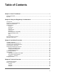
Table of Contents Chapter 1 About This Manual .............................................................................................1 Warnings and Notes ....................................................................................................................................1 Symbols .......................................................................................................................................................1 Chapter 2 Safety and Regulatory Considerations ........
Subsystems ...............................................................................................................................................41 Electronic Subsystem ..........................................................................................................................42 Fluidics Subsystem ............................................................................................................................. 43 Mechanical Subsystem ........................................
Communication Problems ..........................................................................................................................74 Clogs ..........................................................................................................................................................75 Fluid Leaks ................................................................................................................................................75 Sample Probe Problems ....................
MAGPIX® xii
Chapter 1: About This Manual Warnings and Notes The following informational notes and warnings appear as necessary in this manual. NOTE: This message is used to provide general helpful information. No safety or performance issues are involved. CAUTION: This message is used in cases where the hazard is minor or only a potential hazard is present. Failure to comply with the caution may result in hazardous conditions.
TABLE 1.
Chapter 2: Safety and Regulatory Considerations Become familiar with the safety information in this chapter before using MAGPIX. This system contains electrical and mechanical components that, if handled improperly, are potentially harmful. In addition, biological hazards may be present during system operation. Therefore, Luminex recommends that all system users become familiar with the specific safety advisories below in addition to adhering to standard laboratory safety practices.
FIGURE 1. Fuse Caution Label A voltage label appears on the back of MAGPIX. It displays the MAGPIX serial number, model number, power requirements, and manufacturer’s information. FIGURE 2. Serial Number and Voltage Label A label with legal information appears on MAGPIX.
FIGURE 3. Legal Information Because MAGPIX complies with European Union safety requirements, it displays an EC representative label. FIGURE 4. EC Representative Patent information appears on MAGPIX.
FIGURE 5. Patent Testing and Certifications MAGPIX has been tested by MET and complies with safety requirements for the United States and Canada. FIGURE 6. MET Mark In addition, MAGPIX complies with European Union (EU) safety requirements and therefore may be marketed in the Europe Single Market. The following European Union compliance label appears on the back of the MAGPIX instrument.
FIGURE 7. European Union Compliance Label Safety Practices In any situation in which you encounter this symbol, consult this manual or other Luminex documentation to determine the nature of the potential hazard and any necessary actions you must take. CAUTION: The protection provided by the equipment can be impaired or the warranty voided if the Luminex MAGPIX system is used in a manner not specified by the instructions or by Luminex Corporation.
Do not perform any maintenance or cleaning of the electrical components in the system, with the exception of replacing fuses. Observe the fuse caution stated on the fuse caution label. Be aware of the voltage of the instrument. See Regulatory Labels and Warnings on page 3. Indicator Light The lights inside the front panel of MAGPIX indicate the status of the system and are harmless. The blue light-emitting diodes (LEDs) do not emit light in the UV spectrum.
CAUTION: Do not use the heater plate as an incubator. Its purpose is to maintain the temperature of the microtiter plate while the plate is in the MAGPIX instrument. Monitor the heater plate temperature while it is in use. If it overheats, discontinue use and contact Luminex Technical Support. WARNING: The heater plate of the MAGPIX plate carrier may be hot and can cause personal injury if touched. Do not touch the heater plate. Fluids This instrument contains fluids.
1. Remove all specimens and all Luminex MAGPIX reagents. Leave distilled water and household bleach solution diluted to 10% to 20% in water in the off-plate reagent block of the system. 2. Use the software to run a sanitize command with the diluted (10% to 20%) household bleach solution followed by two wash commands with distilled water. 3. Empty the off-plate reagent block and the waste container and clean each with a 10% to 20% bleach solution followed by a distilled water rinse. 4.
Chapter 3: Installation Procedure Before handling or unpacking MAGPIX, make certain that the selected site is appropriate. Refer to the Installation Diagrams on page 12 for handling and site installation requirements and detailed dimensions of MAGPIX.
CAUTION: This overpack is too heavy to be lifted by one person (approximately 119lbs (53.97kg), a three-person lift) and should be moved mechanically. Be careful the overpack is not punctured during any necessary moving. Within the overpack are separate cartons for the PC, the monitor, the 2-pack of Drive Fluid, and the MAGPIX instrument. In addition, a divided tray contains the cables, CDs, and printed material. For the complete list of contents, see Shipping Checklist. FIGURE 9. Inside the Overpack 1.
Installation Procedure 13
Unpacking and Assembling the PC Begin the installation process with the PC. The computer and monitor are in the boxes at the end of the overpack; the monitor stand is in a box underneath the accessory tray. The computer and monitor boxes include all the necessary cords and peripheral devices as well as complete installation instructions. Follow those instructions to set up the PC. To set up the PC: 1. Remove the three boxes containing PC components from the overpack. 2.
1. Remove the MAGPIX carton from the overpack. FIGURE 11. Removing the MAGPIX Carton The MAGPIX instrument is inside a plastic bag and surrounded by foam inserts attached to a corrugated cardboard insert. FIGURE 12. The MAGPIX Carton, Opened 2. Remove MAGPIX from its carton by pulling on the handles that extend from the cardboard insert. NOTE: It is helpful to have another person hold down the carton while you pull out MAGPIX.
FIGURE 13. Pulling MAGPIX from its Carton 3. Put the instrument on a stable, flat surface. This may require two people. 4. Fold down the cardboard panels from each side of the instrument. FIGURE 14. Removing the Packing Materials 5. Pull the plastic bag down from the top. 6. Place MAGPIX onto a lab bench or other flat, stable surface. This may require two people.
1. Locate the cords in the accessory tray of the overpack. FIGURE 15. Power Cord and USB Cable 2. Plug the power cord into the back of the instrument.
3. Connect the USB cable to the PC and to the connector labeled P1 on the back of MAGPIX. Use the top right USB port on the back of the PC. FIGURE 16. Power Cord and USB Cable Connected 4. Connect the barcode scanner (if ordered) to the computer, to a USB port on either the front or back. FIGURE 17.
Preparing MAGPIX for first use includes removing the shipping plug, installing the Drive Fluid, and installing the sample probe. Removing the Shipping Plug Inside the side access door of MAGPIX, a shipping plug holds the sample probe assembly in place. Use the door access tool included in the accessory tray to open the side access door and remove the plug. CAUTION: MAGPIX should not be plugged into a power source when you open this compartment.
1. Locate the door access tool in a small plastic bag in the accessory tray of the overpack. FIGURE 18. Door Access Tool 2. Insert the tool in the side access door latch and turn it one quarter turn clockwise. FIGURE 19.
3. Slide the door to the right. FIGURE 20. Sliding Open the Door 4. Raise the probe assembly and locate the shipping plug. FIGURE 21.
5. Pull the probe holder up, then, holding MAGPIX on the top with one hand to stabilize it, firmly push the probe assembly away from you with your other hand. Be prepared to use some strength. FIGURE 22. Pushing the Probe Assembly 6. With the probe assembly out of the way, lift out the shipping plug. FIGURE 23. Lifting Out the Shipping Plug Installing the Sample Probe MAGPIX comes with two sample probes, but the probe is not pre-installed.
To install the sample probe: 1. Locate the sample probe, which is shipped in a tube in the accessory tray. FIGURE 24. The Sample Probe and Its Container 2. Pull the probe assembly toward you and push it down.
3. Completely unscrew the probe fitting on top of the probe holder by turning it counterclockwise. FIGURE 25. Unscrewing the Probe Fitting 4. Put the probe into the opening left by the probe fitting. It should slip down and catch at the bottom of the opening. FIGURE 26.
5. Reinstall the probe fitting, tightening it until it clicks into place. FIGURE 27. The Sample Probe in Position 6. Close and latch the side access door. Installing the Drive Fluid The overpack includes a carton containing two containers of Drive Fluid. Open the carton and remove one container to install in the instrument.
1. Locate the carton of Drive Fluid containers. FIGURE 28. Drive Fluid Carton and Container 2. Open the carton and remove a container of Drive Fluid.
3. Open the door of the fluid compartment on the front of MAGPIX. FIGURE 29. The Fluid Compartment 4. Pull the Drive Fluid tube and plug (1) in the left side of the fluid compartment forward until it extends outside the compartment. Pull it to the left to allow room to insert the Drive Fluid container. FIGURE 30.
5. Insert the Drive Fluid container half way into the fluid compartment opening and remove the seal. FIGURE 31. Removing the Seal 6. Connect the Drive Fluid tube and plug to the opening on the top of the Drive Fluid container. FIGURE 32.
7. Slide the container into the tray on the left side of the fluid compartment. The container tray is constructed to hold the container in place. FIGURE 33. Sliding in the Drive Fluid Container 8. After the container is fully inserted, check the valve on the front of the waste fluid container to make certain it is securely attached and close the door of the fluid compartment. Powering Up MAGPIX MAGPIX has two on/off switches: a hard power switch and a soft power switch.
1. Plug the power cord from the back of the instrument into a power outlet. NOTE: Luminex recommends the use of a surge protector or UPS device with MAGPIX. For more information, see Uninterruptible Power Supply (UPS) or Surge Protector on page 54. 2. Turn on the hard power switch (1). This is the toggle switch at the lower right corner of the back of MAGPIX. NOTE: The hard power switch controls flow of power to the instrument. FIGURE 34.
3. When you are ready to begin testing, turn on the soft power switch (2) on the front of MAGPIX. The blue LED in the hexagonal window lights up as confirmation that the power is on. MAGPIX requires approximately 45 seconds to start up. NOTE: The soft power switch activates and deactivates the unit. FIGURE 35. The Soft Power Switch 4. After MAGPIX is powered on, use the software to eject the tray carrier to put the off plate reagent block in place.
4. Based on the type of plate you are using, place alignment disks or an alignment sphere in the well. • For a standard 96-well plate - none • For a Filter-bottom plate - two 5.08 mm disks • For a Mylar-bottom plate - two 5.08 mm disks • For a conical (v-shaped) plate - one sphere 5. Click Eject to eject the plate carrier. 6. Place the off plate reagent block on the plate carrier. Make sure it is well seated so that it clips into place. 7.
FIGURE 36. Sample Probe Height Adjustment Revive After Storage Routine NOTE: The Revive After Storage routine is necessary when the system runs for the first time and is recommended when the system has been idle for more than a week. After you have adjusted the sample probe height, run the Revive After Storage (Luminex) routine. 1. Open the Maintenance page, then the Cmds & Routines tab. 2. Select Revive After Storage (Luminex) from the drop-down list.
Calibration - Verification Calibration normalizes the settings for the system and ensures optimal and consistent microsphere classification. Verification uses system controls to ensure that the analyzer is functioning properly with current calibration settings. 1. On the Home page, click System Initialization under Daily Activities. The Auto Maint tab opens. 2. Click the Calibration/Verification option under Automated Maintenance Options section. 3.
5. Select the *.lxl file and click Open. 6. Click OK.
MAGPIX® 36
Chapter 4: Technical Overview This chapter describes the operation, components, subsystems, and technical specifications of MAGPIX. How MAGPIX Operates MAGPIX combines a fluidics system, a mechanical system, an electronic system and an optical system with magnetic microspheres and complex computer analysis to perform multiplex assays. The mechanical system begins the process. An operator places a 96-well microtiter plate on the plate carrier, which transports the plate into the instrument.
FIGURE 37. MAGPIX Front & Right Side 1. Status indicator light 2. Soft on/off switch 3. Access door for plate carrier. 4. Access door for fluid compartment. For a more detailed illustration, see The Fluid Compartment on page 49. 5. Side access door 6.
FIGURE 38. MAGPIX Back & Left Side 1. Communications port (P1) 2. Power input module 3. Rear air filter System Components The following topics describe details of the three components of the Luminex MAGPIX system: software, reagents, and hardware.
Software Luminex xPONENT for MAGPIX software provides complete control of the MAGPIX instrument and performs the analysis. The software requires a dedicated PC. For updated information about the PC or operating system, see Luminex xPONENT for MAGPIX Software User Manual. Under most circumstances, the PC that comes with the MAGPIX system is preloaded with xPONENT for MAGPIX software. Luminex provides a software DVD to use if you need to reinstall the software or need to install it on another computer.
The hardware is shipped with a quick installation guide, a quick software user guide, a CD containing both the software user manual and the hardware installation and user manual, and a DVD containing the software. Reagents xMAP technology requires two kinds of reagents: common laboratory reagents and reagents created especially for Luminex instruments. CAUTION: Adhere to standard laboratory safety practices when handling hazardous, toxic, or flammable reagents and chemicals.
Electronic Subsystem The electronics subsystem provides the power for operation and control of the MAGPIX system and communication between its parts. Power Input Module The power input module contains the input power plug, hard power toggle switch, and fuses. This is the protective earthing point for the MAGPIX system. The mating power cord connector type is IEC-320-C13.
FIGURE 40. Communications Port Printed Circuit Board Assemblies MAGPIX requires a series of printed circuit board assemblies (PCBAs), including four major boards: optics control, XY controller, imaging, and processor. These PCBAs are all contained within the same area as the optical system, are not accessible to the user, and require no user maintenance. Fluidics Subsystem The fluidics subsystem handles the flow of liquid through MAGPIX.
FIGURE 41. Side Access Door FIGURE 42. Interior of Side Access Door Sample Probe Assembly The stainless steel sample probe fits inside a holder. A probe fitting screws into the top of the holder, keeping the probe in place. From the probe, through the fitting, extends a tube that passes through a strain relief and attaches to the sample valve.
syringe pump also enters the sample value, and a tube extends from it into the optical chamber, carrying the sample mixed with Drive Fluid. A wheel pulley, covered by a protective shield, moves the probe assembly along the x axis.
FIGURE 43. Sample Probe Assembly 1. Sample loop 2. Strain relief 3. Probe-to-valve tube (coded black) 4. Valve-to-optical chamber tube (coded red) 5. Sample probe 6. Sample valve 7. Protective cover on wheel pulley 8. Probe holder 9. Probe fitting WARNING: Avoid contact with moving parts.
WARNING: Wear appropriate personal protective equipment when handling parts that come into contact with potentially biohazardous samples. Syringe Pump and Drive Fluid Filter The syringe pump draws fluid from the Drive Fluid container, in the bottom compartment of the instrument. The fluid first passes through the Drive Fluid filter, which removes particles greater than 35 microns in diameter.
FIGURE 44. Syringe Pump and Drive Fluid Filter 1. Drive Fluid filter 2. Plunger 3. Tube from Drive Fluid container 4. Glass cylinder 5. Mounting bracket 6. Plunger guide 7. Syringe pump valve 8.
WARNING: Avoid contact with moving parts. The Fluid Compartment At the bottom of the front panel of MAGPIX, a door folds down to provide access to the fluid compartment. Within that compartment, two trays hold the Drive Fluid and waste fluid containers. Internal sensors monitor the fullness of the waste fluid container and the emptiness of the Drive Fluid container. When either container reaches an unacceptable level, MAGPIX stops.
FIGURE 46. Fluid Compartment, Interior 1. Drive Fluid container in place 2. Waste fluid container in place 3. Valve attaching waste tubing to waste fluid container Mechanical Subsystem x-Axis and y-Axis Movement The MAGPIX mechanical subsystem includes the plate carrier and the assembly that moves the sample probe. The carrier moves along the y axis, to allow the sample probe access to each row of the microtiter plate.
FIGURE 47. MAGPIX Plate Carrier Assembly 1. Microtiter plate area 2.
FIGURE 48. MAGPIX Sample Probe Assembly 1. Pulley wheel that moves sample probe assembly along x-axis (cover removed) 2. Sample probe Air Filters MAGPIX has two air filters, one on the bottom of the instrument and one on the back of the instrument. These filters require periodic cleaning to perform optimally. The filter on the bottom of MAGPIX can be slid out of its holder toward the front of the instrument. This requires lifting up or tilting the instrument.
FIGURE 49. Bottom of MAGPIX showing filter in place in holder FIGURE 50. Back of MAGPIX showing filter in place in holder Optical Subsystem The MAGPIX optical subsystem consists of red and green LED illumination, a CCD-based camera, an imaging chamber, and a magnet to hold the magnetic microspheres in place during the imaging process. The optical subsystem is contained in the same area as the PCBAs. It is not accessible by the user and requires no user maintenance.
Recommended Additional Equipment Successful operation of the Luminex MAGPIX system may require additional equipment. Uninterruptible Power Supply (UPS) or Surge Protector Luminex recommends using either an uninterruptible power supply (UPS) or a surge protector to protect your system from power outages. Use a UPS that provides 585 Watts/ 960 VA for at least 60 minutes.
• Installation Category II • Pollution degree 2 • Temperature control: maintains samples using the heater block at a constant temperature from 35° C to 60° C (95° F to 131° F) +/- 1° C of set point.
Microtiter Plates • Microtiter plate must be 96-well, not to exceed 1” (2.54cm) in height, including heater block. • Microtiter plate must be compatible with the microtiter heater block temperature when the heater block is in use. • All microtiter plates have standard width (85.5mm) and length (127.9 mm). Depth varies depending on the type of well. Maximum allowable depth is 1” (2.54cm). Plates must have minimum 0.06” (1.
Chapter 5: Operational and Maintenance Procedures To ensure accurate test results, properly clean and maintain MAGPIX. Read and follow all instructions in this chapter. To facilitate your maintenance process, print out and use the maintenance logs. See Short Term Maintenance - One Week on page 71.
The side compartment of MAGPIX contains the majority of user-maintainable components. The access door to this compartment must remain latched during operation of the instrument. Opening the access door requires a special tool provided with the MAGPIX system. FIGURE 51. Side Access Door Latch To open the latch: 1. Turn off and unplug MAGPIX. 2. Insert the latch tool into the slot of the latch and turn it clockwise. 3. Slide the door to the right.
Initializing MAGPIX Initialize MAGPIX at the start of each day. Refer to the MAGPIX User Quick Guide for instructions for setting up the daily initialization. Initialization requires less than five minutes and includes a quick system self-check. Verifying MAGPIX Perform verification using the xPONENT for MAGPIX software. Refer to the xPONENT for MAGPIX Software User Manual or online help.
4. Unscrew the cap on top of the waste fluid container to drain out the fluid. NOTE: Discard the waste fluid in accord with all local, state, federal, and country-specific biohazard handling regulations. 5. Insert the second, dry waste fluid container in the fluid compartment. NOTE: Make sure the empty waste fluid bottle is dry or the empty bottle will continue to send a "waste bottle full" message. WARNING: Waste fluid can contain biohazardous infectious agents.
1. Execute STOP if a plate is running. Refer to the software manual for instructions. 2. Turn off MAGPIX and unplug the power cord. 3. Remove the sample probe. a. Open the side access door of MAGPIX. b. Unscrew the probe fitting on top of the probe completely. c. Grasp the probe gently and push up. d. Lift the probe out of the top of the probe holder. FIGURE 52. Probe Assembly 1. Probe fitting - Unscrew and remove in step 3. 2. Probe holder 3. Probe - Push up gently and lift out of holder in step 3. 4.
5. Replace the sample probe and tightly screw in the probe fitting until it clicks. 6. Use the software to perform an automatic probe height adjustment. NOTE: Perform an automatic probe height adjustment any time the probe is reinstalled after removal. Performing a Visual Inspection Inspect MAGPIX weekly. Make sure the instrument is idle, so there are no moving parts. Open the MAGPIX side access door and fluid compartment door and visually inspect for leaks, corrosion, and other signs of improper function.
1. Turn off MAGPIX and unplug the power cord. 2. Clean all exterior surfaces with mild detergent, followed by a household bleach solution diluted to 10% to 20%, followed by distilled water. 3. Open the side access door of the instrument. 4. Clean all accessible surfaces with detergent, followed by the household bleach solution (10% to 20%), followed by distilled water. WARNING: Avoid contact with the tubing and electronic parts of the instrument. 5. Dry any unpainted metal surfaces to prevent corrosion. 6.
6. Reinstall filters. 7. Plug in the power cord and turn on MAGPIX. MAGPIX® 64 FIGURE 54. Bottom of MAGPIX, Filter holder FIGURE 55.
Replacing the Syringe Seal When you replace a syringe seal, also replace the black O-ring that fits inside it. One package contains four of each. To replace the syringe seal: 1. Turn off MAGPIX and unplug the power cord. WARNING: The plunger guide does NOT deactivate while the seal is being changed; unplugging is necessary to avoid injury. 2. Open the side access door of MAGPIX. 3. Locate the syringe (glass cylinder with a metal rod plunger). 4. Push the plunger guide down.
10. Screw the syringe back into its housing. FIGURE 56. The Syringe 1. Syringe housing 2. Metal rod plunger 3. Syringe seal, containing black O-ring 4. Glass cylinder 5. Plunger guide 11. Return the plunger guide to its original position. The bottom of the plunger fits into the indentation in the plunger guide. 12. Plug in the power cord and turn on MAGPIX. 13. Use the software to run the prime command twice, watching for any leaks in the syringe area. 14. Close the side access door.
FIGURE 57. Sample Probe Tube 1. Sample probe tube (color-coded black at valve end) 2. Valve 3. 1/4-28 flat-bottom fittings 4. Strain relief 5.
FIGURE 58. Sample Probe Tube Assembly 1. 1/4-28 Flat-bottom fitting 2. Tube between probe and valve 3. Probe fitting To replace the sample probe tube: 1. Turn off MAGPIX and unplug the power cord. 2. Open the side access door on MAGPIX and locate the probe assembly. 3. Unscrew the probe fitting completely. The sample probe tube is connected to it. 4. Unscrew the 1/4-28 flat-bottom fitting at the valve end of the sample probe tube. The sample probe tube is connected to it.
5. Ensure that the Drive Fluid filter orientation (top and bottom) matches the following figure and reattach the tubing to the ends of the new filter. Tighten both fittings until they click. FIGURE 59. Drive Fluid Filter 1. Tube attachments (Unscrew in step 3) 2. Filter 3. Tube attachments (Unscrew in step 3) 4. Mounting bracket 6. Press the new filter into the mounting bracket. 7. Close the side access door. 8. Plug in the power cord and turn on MAGPIX. 9. Use the software to run the Prime command twice.
Replacing Fuses Periodically, you may need to replace a fuse on MAGPIX. Use fuses with the following specifications: F2A, 250 V The fuse cartridge will accept either 5 mm x 20 mm or 0.25” x 1.25” fuses. Fuses are available from Luminex Corporation. Replacing a fuse requires access to the back of MAGPIX. DANGER: To avoid serious injury or death by electric shock, turn off MAGPIX and unplug it from the wall before replacing a fuse. To replace a fuse: 1. Unplug the power cable from the instrument. 2.
twice yearly), and annual maintenance (two tasks yearly). For each item listed at the left, enter your initials under each date on which you perform the task.
Replace Drive Fluid filter Replace sample probe tube MAGPIX® 72
Chapter 6: Troubleshooting Procedures Troubleshooting procedures help users identify and remedy problems with the instrument. Overview To troubleshoot a problem, locate the problem in one of the sections in this chapter, explore the possible causes, and take the described corrective action.
Power Supply Problems Power supply problems often involve a blown fuse, faulty electronic component, or disconnected cable. CAUTION: Whenever you deal with a potential electrical problem, be careful to avoid electrical shocks. Problem Possible Cause Corrective Action MAGPIX will not turn on. The power cord is disconnected. Plug in the power cord. The hard power switch on the back of the instrument is not turned on. Turn on the switch. No voltage is coming from the electrical outlet.
Clogs Often, a clog somewhere in MAGPIX is the cause of a problem with calibration, verification, or data acquisition. To determine whether there is a clog, run performance verification to see if the fluidics function is operating properly. In the event you encounter a problem that is clogrelated, use the following procedure. To troubleshoot a possible clog: 1. Clean and adjust the sample probe. Cleaning the Sample Probe on page 60. 2. Perform the procedure for removing clogs. Removing Clogs on page 62. 3.
Problem Possible Cause Corrective Action The sample probe leaks. The sample probe is clogged. Clogs on page 75. The sample probe fitting is loose. Tighten the fitting until it clicks. The sample valve has one or more loose fittings. Hand tighten the sample valve fittings. The sample valve is faulty. Contact Technical Support. The syringe seal leaks. The seal is worn out or faulty. Replace the syringe seal. Replacing the Syringe Seal on page 65. The syringe valve leaks.
Calibration Failure Calibration problems can result from a variety of causes, many of them easily correctable human errors. The following error codes are associated with calibration failure: • Error code 59: Normalizer has a zero value. Re-calibrate. • Error code 2054: Insufficient bead count, beads may be out of focus. Self-test may help by re-homing camera. • Error code 8226: Bubbles sense error. • Error code 2091: General hardware error was encountered. Self-test to confirm.
Possible Cause Corrective Action There is air in the instrument. (Error code 8226) Perform an automatic sample probe height adjustment. Use the software to run a prime command three times, an alcohol flush command twice, then a wash command three times with distilled water. Make sure the Drive Fluid coil is not pinched. The sample valve is faulty. Contact Technical Support. There is a problem internal to the instrument. (Error code 2091) Review the log of calibration reports.
Possible Cause Corrective Action The verification lot is expired. Use an unexpired bottle of verification microspheres. The verification microspheres have been diluted. Substitute undiluted verification microspheres. The verification microspheres are photobleached. Use a different bottle of verification microspheres, one which has been protected from light during storage. Possible Sample Probe Causes: The sample probe height is incorrect. Perform an automatic sample probe height adjustment.
Possible Cause Corrective Action There are too few or too many xMAP microspheres in the well. Ensure that there are 2000 to 5000 beads per bead set per well. The xMAP microspheres have expired. Substitute an unexpired bottle of xMAP microspheres. The xMAP microspheres are photo bleached. Substitute xMAP microspheres that are not photo bleached. Possible Sample Probe Causes: The sample probe height is incorrect. Perform an automatic sample probe height adjustment. The sample probe is clogged.
• MAGPIX calibrators • MAGPIX performance verifiers • assay standards • assay controls • error messages Review the log of calibration reports routinely to detect trends. Use MAGPIX performance verifiers to check the success of the instrument calibration and to troubleshoot. If there is a problem with kit results, MAGPIX performance verifiers can help determine if the problem is related to the instrument. If calibration and verification are successful, contact the kit manufacturer.
Appearance Description Possible Cause Corrective Action MagPlex verifiers are anywhere outside of their region. MAGPIX is out of calibration. Recalibrate and verify. The dot plot is elongated, horizontally or vertically. MagPlex beads fail to form a tight population within their regions. The dot plot is wide and possibly extends horizontally, vertically, or diagonally to the left.
Appendix A: Storage If you need to put MAGPIX in long-term storage - anything longer than a month - or prepare it for use after removing it from long-term storage, use the following procedures. Storing MAGPIX This procedure explains the steps you should take before placing MAGPIX into long-term storage. To prepare MAGPIX for storage: 1. Use the software to perform a preparation for storage routine. 2.
3. Turn on MAGPIX and watch for the following indications of correct response: • Air blows out of the fans. • The syringe inside the side access door of MAGPIX initializes. 4. Turn on the PC and start up the software. 5. Use the software to run a Revive after Storage routine.
Appendix B: Shipping If a serious problem arises with MAGPIX, it may be necessary to return it to Luminex Corporation for repairs. If Luminex Technical Support directs you to return MAGPIX, the Technical Support representative will provide you with all necessary information as well as a Return Material Authorization (RMA) number. CAUTION: Before the instrument is returned, perform two procedures: Decontaminate the instrument and prepare the instrument for shipping.
No Printed Name____________________________________________________ Signature_______________________________________________________ Company/Institution_______________________________________________ Date________________ Instrument Serial No.
Appendix C: Part Numbers Hardware Product Description Customer Number Luminex MAGPIX with xPONENT for MAGPIX MAGPIX-XPON4.1 Access Door Tool CN-0264-01 Syringe Seal (Qty 4) CN-0014-01 Fuse 2AMP 250V Fast Acting (Qty 10) CN-0019-01 Sample Probe Needle CN-0221-01 Heater Block, 96 Wellplate CN--224-01 Cable, USB (A to B) CN-0271-01 Air Filter 4.5 x 4.
Reagents MAGPIX® 88 Product Description Customer Number MAGPIX Calibration Kit MPX-CAL-K25 MAGPIX Performance Verification Kit MPX-PVER-K25 MAGPIX Drive Fluid, 4-pack MPXDF-4PK
Index "microtiter plate 76 A access doors 43 air in instrument 79 automatic probe height adjustment when to perform 62 B biohazard biosafety procedures 57 biohazard warning 57, 60 C certification European Union 6 clog 75 clog removal procedure 62 clogtroubleshoot procedure 75 communication cable 74 definition 74 problems 74 D draining reservoir procedure 85 E exterior cleaning procedure 62 F failure to turn on 74 fluidics subsystem 43 fuse blown 74 burned out 74 replacement 70 L leaks 75 Luminex em
sheath fluid brand 59 sheath fluid container 59 shipping checklist 85 return 85 short circuit 74 sodium hydroxide warning 60, 62 storage preparation procedure 83 removal procedure 83 syringe seal leak 76 syringe valve leak 76 T technical support, Luminex 73–75, 85 MAGPIX® 90 testing MET 6 V verification microspheres uses 81 visual inspection procedure 62 W warning electric shock 42, 70, 74 waste fluid container emptying 59
LUMINEX CORPORATION 12212 Technology Boulevard Austin, Texas 78727-6115 U.S.A.