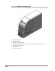
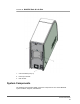
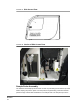
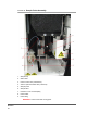
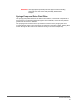
FIGURE 43.
Sample Probe Assembly
1. Sample loop
2. Strain relief
3. Probe-to-valve tube (coded black)
4. Valve-to-optical chamber tube (coded red)
5. Sample probe
6. Sample valve
7. Protective cover on wheel pulley
8. Probe holder
9. Probe fitting
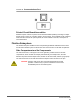
WARNING: Avoid contact with moving parts.
MAGPIX
®
46