
User's Manual


3
PRELIMINARY—NOT FOR RELEASE
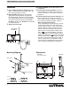
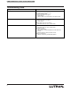
Contact Closure Input Wiring Diagram
SBT
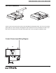
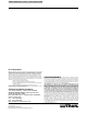
Port Cover Installation
The Port Cover can be removed for access to the Reset Button and Diagnostic LEDs. The cover is removed by
gently pulling up on the front edge to disengage the snaps. Replace the cover by inserting the two tabs on the
back of the cover into the slots on the SBT. Gently press down on the front edge to engage the snaps.
Slots
Tab
Tab
Press
Down
Input 1
Input 2
Security
Input