D3 Installation Guide Models D3-FXRD D3-FXSQ D3-ADRD D3-ADSQ D3-WWRD D3-WWSQ
! Warning Shock Hazard. May result in serious injury or death. Turn power OFF at circuit breaker or remove fuse. Damage to this product caused by wiring with power on voids the warranty. Due to the risk of electric shock, a licensed electrician should install this power supply unit in strict compliance with the National Electrical Code and any state or local code which may apply. FCC/ IC Information: This device complies with part 15 of the FCC Rules and Industry Canada license-exempt RSS standard(s).
Contents Product Overview 4 Included Components/Supported Models 5 Included Components 5 Supported Models 5 Specifications 6 Installation 7 Part 1: Mount the D3 7 Part 2: Wire the Fixture 12 Part 3: Installing Sheetrock 13 Part 4: Apply Spackle Flange Trim Retainer (Mud-In Only) 13 Part 5: Apply Joint Compound 14 Part 6: Apply Trim 14 Additional Operations 16 Troubleshooting 18 Warranty & Tech Support 19 P/N 040444 Rev D © 2019 Ketra, Inc.
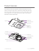
Product Overview Ketra’s D3 family includes fixed, adjustable, and wall-wash downlights. Every model features a low-profile housing, wireless communication, and field-replaceable optics and electronics. With a wealth of trim and optic accessories, the D3 is ideal for a large variety of applications. It uses a fully-tunable spectrum capable of delivering highquality white, saturated, and pastel light.
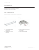
Included Components/Supported Models Included Components Housing with Emitter & Optic (Models as specified) ( 2 ) Butterfly Brackets ( 2 ) Nailer Bars ( 3 ) Wire Nuts Trim (Model as specified) Supported Models D3-FXRD D3-ADRD D3-WWRD D3-FXSQ D3-ADSQ D3-WWSQ 1 For instructions on setting default states in Design Studio, see the Design Studio Manual available on our website.
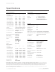
I N S TA L L AT I O N Specifications Optical Performance Environmental Delivered Lumen Output Operating Temperature 0 - 40 °C Storage Temperature -20 - 80 °C Humidity 0 - 95%, Non-condensing Certification UL, cUL, RoHS, FCC Class B Location UL Damp Location, UL Wet Location Available with Lens Trim Beam Angle (1"/ 25.
I N S TA L L AT I O N Installation All touch-points inside the D3 housing are colored red. All customer-accessible screws are Phillips. Part 1: Mount the D3 Mounting can be done with either nailer bars or butterfly brackets.
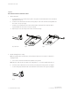
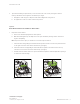
I N S TA L L AT I O N Option 1 M O U N T I N G W I T H N A I L E R BA R S 1. Attach nailer bars a. If ceiling thickness is ¾” (19.05 mm) or greater: Use pliers to break off the tabs at the end ofboth nailer bars. (see fig. 1) b. Insert the inner nailer bar into the three housing clasps on the end of the D3 housing. Make sure the screw is on top. (see fig. 2) c. Insert the outer nailer bar into the same housing clasps, locking the inner andouter halves together. Make sure the screw is on top.
I N S TA L L AT I O N 3. Optional: If installing a square fixture, loosen the collar's two outer screws, freeing the collar for rotation, which then can be aligned to the fixtures per design. a. Realign the collar using its v-shaped notches and an alignment string or laser. b. Re-tighten the screws to lock the collar’s new position. Option 2 M O U N T I N G W I T H B U T T E R F LY B R AC K E T S 1. Reposition emitter chassis a. Remove the cardboard plug from the D3’s aperture. b.
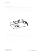
I N S TA L L AT I O N 2. Attach butterfly brackets a. Outside the housing, undo the red wing nut and washer attached to the first butterfly bracket’s bolt. b. Run the bracket’s bolt through the hole in the side of the housing. (see fig. 7) c. Reaching into the housing, thread the washer and red wing-nut back onto the bolt, fixing the bracket in place. d. Repeat steps 5-7 for the second butterfly bracket. fig. 7 3. Restore original emitter chassis conditions a.
I N S TA L L AT I O N 4. Mount downlight in ceiling Note: For optimal radio communication, ensure that the radio dome is not above or adjacent to anything metallic. a. Use bar stock or C-Channels (not provided) to mount the D3 in the ceiling. The supports should go through the holes in the butterfly brackets and can be used to suspend the D3 without screws. (see fig. 8) Note: After mounting, the D3’s collar will need to be flush to the ceiling plan or ~1/16th (1.5875 mm) inches above it. b.
I N S TA L L AT I O N Part 2: Wire the Fixture 1. Run power to junction box a. A. Remove the junction box’s outer cover by pressing down on the outer latch and pulling the cover toward you. Note: A licensed electrician should perform all the wiring tasks. All electrical connections must be made within the junction box. b. Run the conduit in (and out, if this is one downlight in a sequence). Note: Maximum of ( 8 ) 12 AWG through branch circuit conductors suitable for 75˚ C permitted in the box. c. 2.
I N S TA L L AT I O N Part 3: Installing Sheetrock 1. Ensure that the aperture is plugged with the cardboard insert to protect the optic. 2. Cut properly-sized hole in sheetrock before installing sheetrock. Reference table for sizes. 3. Type Hole shape and size Mud-In Circle with 5.5” (139.7 mm) diameter Flanged with square aperture Square with 4” (101.6 mm) length/width Flanged with round aperture Circle with 4” (101.
I N S TA L L AT I O N Part 5: Apply Joint Compound 1. Do a skim coat up to the aperture rim using a joint compound. (For mud-in versions, cover the flange but not the retainer.) For best results, use a full ceiling float. (see fig. 10) fig. 10 2. Sand and finish the final surface before removing the aperture plug. Clean the internal surfaces of the trim retainer with a clean rag and isopropyl alcohol. Part 6: Apply Trim Mud-in and flanged downlights have different processes for applying their trims.
I N S TA L L AT I O N 2. Applying trim to flanged downlight a. If your ceiling’s substrate is thicker than 5/8”- 1” (16.129 - 25.4 mm), adjust the springs on either side of your trim: a) Using a #1 screwdriver, loosen the screw holding the spring in place; b) raise the spring as high (as far from the bottom of the trim) as it will go; c) re-tighten the screw. (see fig. 12) 8 7 5 6 4 2 3 REV. 01 1 REVISIONS ECO DESCRIPTION DATE APPROVED INITIAL RELEASE D D C C B B fig.
Additional Operations 1. Re-Aiming the Optic a. Remove the trim by pulling the trim directly down from the housing. b. Unlock the emitter chassis: reach into the D3’s housing and unlock tilt lock and rotation lock levers (both colored red). (see fig. 14) c. Use the degree indicators to determine degree of rotation (square trim only) and tilt. Rotation Lock and Release (see Locked fig.
A D D I T I O N A L O P E R AT I O N S 3. Replacing the Optic a. Remove the trim by pulling the trim directly down from the housing. b. Ensure that the emitter chassis is locked. c. Grab optic and twist counterclockwise to unlock. Pull toward you to remove. d. Install replacement optic, twisting clockwise to lock. (see fig.
Troubleshooting The D3 uses built-in tests to check wiring and wireless connectivity. These tests run each time the D3 turns on, and may take several minutes. Note: The D3 will NOT run these tests while provisioned to a Design Studio installation. If the D3 find a problem, it will let you know by emitting a corresponding color or, if no emitter is connected, by ashing the indicator lights on its power supply.
Warranty & Tech Support Limited warranty terms can be found at: www.ketra.com/warranty For questions and technical support please contact: (844) 588-6445 ketrasupport@lutron.com P/N 040444 Rev D © 2019 Ketra, Inc.
31 E. Stassney Ln. dg. 13, Suite 400 ustin, TX 78744 6231 E. Stassney Ln. Bldg. 13, Suite 400 Austin, TX 78744 P/N 040444 Rev D ketra.com 512.872.4349 P/N 040444 RevA ketra.