
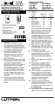
Installation Guide

4A. Single-pole wiring
(See Single-Pole Wiring Diagram)
• Connect the bare or green ground wire
of the dimmer to the bare or green
ground wire in the wallbox.
• Using a wire connector provided, cap off
the violet wire. This wire is only used in
a 3-way installation.
• Connect the white dimmer wire to the
neutral wire in the wallbox.
• Connect the blue dimmer wire to the
120V or 277V supply (hot) wire.
• Connect the red dimmer wire to the wire
going to the black wire of the ballasts.
• Connect the yellow dimmer wire to the
wire going to the orange wire of the
ballasts.
4B. 3-way wiring
(See 3-Way Wiring Diagram)
• Connect the bare or green ground wire
of the dimmer to the bare or green
ground wire in the wallbox.
• Connect the white dimmer wire to the
neutral wire in the wallbox.
• Connect the blue dimmer wire to one of
the two wires coming from the other
switch location.
• Connect the violet dimmer wire to the
second wire coming from the other
switch location.
• Connect the red dimmer wire to the wire
going to the black wire of the ballasts.
• Connect the yellow dimmer wire to the
wire going to the orange wire of the
ballasts.
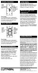
5. Mount and align dimmer. Do not pinch
wires.
6. Screw on faceplate.
7. Turn power ON.
ON
OFF
ON
OFF
ON
OFF
ON
OFF
ON
OFF
ON
OFF
1/2"or 5/8"
Before Installation
CAUTION: Check new installations for short
circuits BEFORE installing the fluorescent
dimmer. Turn power OFF at circuit breaker
or fusebox. Connect a standard switch as
shown in the Test Switch Wiring Diagram.
Turn power ON. If lights do not come on, a
break in the wiring exists. If the breaker
trips, there is a short in the wiring. If
necessary, turn power OFF and correct any
wiring problems, recheck the circuit, then
proceed to Installation. Warranty is void if
dimmer is turned ON in a shorted circuit.
Installation
1. WARNING: Turn power OFF at circuit
breaker or remove fuse.
2. Remove test switch from wallbox.
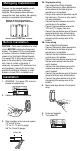
3. Strip insulation or trim wires to expose
1/2" or 5/8" of wire:
1/2" for 10, 12, and 14 gauge.
5/8" for 16 and 18 gauge.
Remove all inner side sections
(shaded) in any ganged installation.
Do not remove outer side sections.
Multigang Installations
Dimmers can be grouped together or with
standard switches under a common
wallplate. When ganging these dimmers,
remove the inner side sections. No capacity
derating is required for these dimmers.