SD card real time data logger DISSOLVED OXYGEN METER Model : DO-5512SD Your purchase of this DISSOLVED OXYGEN METER with SD CARD DATA LOGGER marks a step forward for you into the field of precision measurement. Although this meter a complex and delicate instrument, its durable structure will allow many years of use if proper operating techniques are developed. Please read the following instructions carefully and always keep this manual within easy reach.
TABLE OF CONTENTS 1. 2. 3. 4. FEATURES.................................................................. 1 SPECIFICATIONS.........................................................2 FRONT PANEL DESCRIPTION.......................................5 DO ( Dissolved Oxygen ) MEASURING and CALIBRATION PROCEDURE...................................7 4-1 Dissolved Oxygen measurement............................. 7 4-2 Calibration.............................................................10 4-3 Probe maintenance.......
1. FEATURES * Precision Dissolved Oxygen measurement * Dissolved oxygen : 0 to 20.0 mg/L. * Dissolved oxygen meter use the polar graphic type oxygen probe with temperature sensor, high precision measurement for Dissolved Oxygen ( DO ) and temperature measurement. * Heavy duty dissolved oxygen probe, probe head can connect with BOD bottle. * DO use the automatic Temp. compensation. * DO meter build in " % SALT " & " Mountain Height " compensation value adjustment.
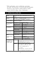
* Wide applications: water conditioning, aquariums, beverage, fish hatcheries, food processing, photography, laboratory, paper industry, plating industry, quality control, school & college, water conditioning. 2. SPECIFICATIONS Circuit Custom one-chip of microprocessor LSI circuit. Display LCD size : 52 mm x 38 mm LCD with green backlight ( ON/OFF ). Measurement Dissolved Oxygen Air oxygen ( for reference only ) Measurement Dissolved Oxygen 0 to 20.0 mg/L ( liter ). & Range Oxygen in Air 0 to 100.0 %.
Oxygen Probe Memory Card Advanced setting The polarographic type oxygen probe with temp. sensor. SD memory card. 1 GB to 16 GB. Data Hold Memory Recall Sampling Time of Display Data Output Freeze the display reading. Maximum & Minimum value. Approx. 1 second.
Power Current Normal operation ( w/o SD card save data and LCD Backlight is OFF) : Approx. DC 14 mA. When SD card save the data and LCD Backlight is OFF) : Approx. DC 37 mA. * AIf LCD backlight on, the power consumption will increase approx. 12 mA. Weight Dimension Accessories Included Optional probe and accessories Meter Probe Meter 489 g/1.08 LB. 335 g/0.74 LB 177 x 68 x 45 mm (7.0 x 2.7x 1.9 inch) Probe 190 mm x 28 mm Dia. ( 7.5" x 1.1" Dia. ) * Oxygen probe ( OXPB-11 )............ 1 PC.
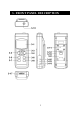
3.
3-1 Display 3-2 Power Button ( Backlight Button ) 3-3 Hold Button ( ESC Button ) 3-4 REC Button ( Enter Button ) 3-5 ▲ Button 3-6 ▼ Button ( Function Button ) 3-7 Time Button 3-8 Logger Button ( SET Button, Sampling check ) 3-9 Stand 3-10 Battery Compartment/Cover 3-11 Battery Cover Screw 3-12 Tripod Fix Nut 3-13 DO Probe Socket 3-14 DC 9V Power Adapter Input Socket 3-15 Reset Button 3-16 RS-232 Output Terminal 3-17 SD card socket 6
4. DO ( Dissolved Oxygen ) MEASURING and CALIBRATION PROCEDURE 4-1 Dissolved Oxygen measurement Fig. 2 1) Prepare the Oxygen Probe ( standard probe, DOPB-11 ), install the " Probe Plug " ( 4-1, Fig. 2 ) into the " DO Socket " ( 3-13, Fig. 1 ). 2) Power on the meter by pressing " Power Button " ( 3-2, Fig. 1 ) once.
Calibration at first ! If it is the first time to use the Dissolved Oxygen meter or after a certain period to use the meter again, then it should to execute the calibration procedures at the first. For the measurement precisely consideration, it recommend to make the calibration before each measurement. Calibration procedure, refer to chapter 4-2, page 10. 4) a.
6) Display will show the Dissolved Oxygen values ( mg/L ) at the same time the bottom display will show the Temp. value of the measured solution. 7) Rinsed the probe accurately with normal tap water after each series of measurement. Oxygen in the air During the DO measurement, press the " Function Button " ( 3-6, Fig. 1 ) once, the display unit will show " %O2 " instead of " mg/L " , it show the air Oxygen value for reference.
4-2 Calibration 1) Install the " Probe Plug " ( 4-1, Fig. 2 ) into the " DO Socket " ( 3-13, Fig. 1 ). 2) Power on the meter by pressing " Power Button " ( 3-2, Fig. 1 ) once. Press the " Function Button " ( 3-6, Fig. 1 ) once, to let Display unit will show " %O2 " instead of " mg/L ". 3) Wait for approx. 5 minutes at least until the display reading values become stable & no fluctuation. 4) Use the two fingers to press the " REC Button " ( 3-4, Fig 1 ) and HOLD Button " ( 3-3, Fig.
4-3 Probe maintenance User first time to use the meter Intend to let the DO probe keep the best condition, when user receive the Oxygen Probe, it should fill the Probe's Electrolyte at first. User already use the probe for a certain period : Whenever user can not calibrate the meter properly or the meter's reading value is not stable, please check the oxygen probe to see if the electrolyte in the probe head container is run out or the diaphragm ( probe head with diaphragm set) exist problem ( dirty ).
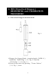
Probe-filling Electrolyte, OXEL-03 1) Unscrew the " Probe head " ( 5-3, Fig 3 ). 2) Pour out the old Electrolyte from the container of the " Probe head ". 3) Fill the new Electrolyte ( OXEL-03 ) into the container of the " Probe head " . 4) Screw the " Probe head " ( 5-3, Fig 3 ) into the probe body. 5) When not use the Fig. 3 probe, should insert the " Probe head " into the " Probe protection cover " 5-1 Probe handle ( 4-5, Fig. 2 ) 5-2 Temp.
5. OTHER FUNCTION 5-1 Data Hold During the measurement, press the " Hold Button " ( 3-3, Fig. 1 ) once will hold the measured value & the LCD will display a " HOLD " symbol. Press the " Hold Button " once again will release the data hold function. 5-2 Data Record ( Max., Min. reading ) 1) The data record function records the maximum and minimum readings. Press the " REC Button " ( 3-4, Fig. 1 ) once to start the Data Record function and there will be a " REC. " symbol on the display. 2) With the " REC.
5-3 LCD Backlight ON/OFF After power ON, the " LCD Backlight " will light automatically. During the measurement, press the " Backlight Button " ( 3-2, Fig. 1 ) once will turn OFF the " LCD Backlight ". Press the " Backlight Button " once again will turn ON the " LCD Backlight " again. 6. DATALOGGER 6-1 Preparation before execute datalogger function a. Insert the SD card Prepare a " SD memory card " ( 1 GB to 16 GB, optional ), insert the SD card into the " SD card socket " ( 3-17, Fig. 1).
6-2 Auto Datalogger ( Set sampling time ≧ 1 second ) a. Start the datalogger Press the " REC Button ( 3-4, Fig. 1 ) once , the LCD will show the text " REC ", then press the " Logger Button " ( 3-8, Fig. 1 ), the bottom text " DATALOGGER " will flashing, at the same time the measuring data along the time information will be saved into the memory circuit. Remark : * How to set the sampling time, refer to Chapter 8-3 page 23. * How to set the beeper sound is enable, refer to Chapter 8-5, page 24. b.
6-3 Manual Datalogger ( Set sampling time = 0 second ) a. Set sampling time is to 0 second Press the " REC Button ( 3-4, Fig. 1 ) once , the LCD will show the text " REC ", then press the " Logger Button " ( 3-8, Fig. 1 ) once, the bottom text " DATALOGGER " will flashing once and Beeper will sound once, at the same time the measuring data along the time information will be saved into the memory circuit. The lower Display will show the Position ( Location ) no. and saved into the SD card too.
6-4 To check the time information During the normal measurement screen ( not execute the Datalogger ), 1) If press " Time Button " ( 3-7, Fig. 1 ) once , the lower LCD display will present the time information of Hour/Minute/Second ( h.m.s ) in the lower Display. 2) If press " Time Button " ( 3-7, Fig. 1 ) once again , the lower LCD display will present the time information of Year/Month/Date ( yy.mm.dd ) in the lower Display. 3) If press " Time Button " ( 3-7, Fig.
2) If the first time to execute the Datalogger, under the route DOA01\, will generate a new file name DOA01001.XLS. After exist the Datalogger, then execute again, the data will save to the DOA01001.XLS until Data column reach to 30,000 columns, then will generate a new file, for example DOA01002.XLS 3) Under the folder DOA01\, if the total files more than 99 files, will generate anew route, such as DOA02\ ........ 4) The file's route structure : DOA01\ DOA01001.XLS DOA01002.XLS .....................
7. Saving data from the SD card to the computer ( EXCEL software ) 1) After execute the Data Logger function, take away the SD card out from the " SD card socket " ( 3-17, Fig. 1 ). 2) Plug in the SD card into the Computer's SD card slot ( if your computer build in this installation ) or insert the SD card into the " SD card adapter ". then connect the " SD card adapter " into the computer. 3) Power ON the computer and run the " EXCEL software ".
EXCEL data screen/graphic screen ( for example ) EXCEL graphic screen ( for example 3, graphic ) 20
8. ADVANCED SETTING Under do not execute the Datalogger function, press the " SET Button " ( 3-8, Fig. 1 ) continuously at least two seconds will enter the " Advanced Setting " mode. then press the " SET Button " ( 3-8, Fig. 1 ) once a while in sequence to select the eight main function, the display will show : Sd F..... SD memory card Format dAtE......Set clock time ( Year/Month/Date, Hour/Minute/ Second ) SP-t...... Set sampling time ( Hour/Minute/Second ) PoFF..... Auto power OFF management bEEP.....
8-1 SD memory card Format When the lower display show " Sd F " 1) Use the " ▲ Button " ( 3-5, Fig. 1 ) or " ▼ Button " ( 3-6, Fig. 1 ) to select the upper value to " yES " or " no ". yES - Intend to format the SD memory card no - Not execute the SD memory card format 2) If select the upper to " yES ", press the " Enter Button " ( 3-4, Fig.
2) After set all the time value ( Year, Month, Date, Hour, Minute, Second ), press the " SET Button " ( 3-8, Fig. 1 ) once will save the time value, then the screen will jump to Sampling time " setting screen ( Chapter 8-3 ). Remark : After the time value is setting, the internal clock will run precisely even Power off if the battery is under normal condition ( No low battery power ). 8-3 Set sampling time ( Hour/Minute/Second ) When the upper display show " SP-t " 1) Use the " ▲ Button " ( 3-5, Fig.
8-4 Auto power OFF management When the lower display show " PoFF " 1) Use the " ▲ Button " ( 3-5, Fig. 1 ) or " ▼ Button " ( 3-6, Fig. 1 ) to select the upper value to " yES " or " no ". yES - Auto Power Off management will enable. no - Auto Power Off management will disable. 2) After select the upper text to " yES " or " no ", press the " Enter Button " ( 3-4, Fig. 1 ) will save the setting function with default.
8-6 Decimal point of SD card setting The numerical data structure of SD card is default used the " . " as the decimal, for example "20.6" "1000.53" . But in certain countries ( Europe ...) is used the " , " as the decimal point, for example " 20,6 " "1000,53". Under such situation, it should change the Decimal character at first. When the lower display show " dEC " 1) Use the " ▲ Button " ( 3-5, Fig. 1 ) or " ▼ Button " ( 3-6, Fig. 1 ) to select the upper text to " bASIC " or " Euro ". bASIC - Use " .
2) After Display unit is selected to " C " or " F ", press the " Enter Button " ( 3-4, Fig. 1 ) will save the setting function with default. 8-8 Set DO salt% compensation value When the lower display show " SALt " 1) This function only for the DO ( Dissolved oxygen ) mode of adjusting the probe's salt% compensation value. The default value is 0% salt. 2) Use the " ▲ Button " ( 3-5, Fig. 1 ) or " ▼ Button " ( 3-6, Fig.
8-10 Set DO height ( feet ) compensation value When the lower display show " Highf " 1) This function only for the DO ( Dissolved oxygen ) mode of adjusting the probe's height compensation value in feet unit. The default value is 0 FEET. 2) Use the " ▲ Button " ( 3-5, Fig. 1 ) or " ▼ Button " ( 3-6, Fig. 1 ) to select the upper value to the desired height compensation value ( feet ), then press the " Enter Button " ( 3-4, Fig. 1 ) will save the setting value temporally.
9. POWER SUPPLY from DC ADAPTER The meter also can supply the power supply from the DC 9V Power Adapter ( optional ). Insert the plug of Power Adapter into " DC 9V Power Adapter Input Socket " ( 3-17, Fig. 1 ). The meter will permanent power ON when use the DC ADAPTER power supply ( The power Button function is disable ). 10. BATTERY REPLACEMENT 1) When the left corner of LCD display show " ", it is necessary to replace the battery. However, in-spec.
12. RS232 PC SERIAL INTERFACE The instrument has RS232 PC serial interface via a 3.5 mm terminal ( 3-16, Fig. 1 ). The data output is a 16 digit stream which can be utilized for user's specific application. A RS232 lead with the following connection will be required to link the instrument with the PC serial port. Meter PC (9W 'D" Connector) Center Pin..........................Pin 4 (3.5 mm jack plug) Ground/shield.......................Pin 2 2.
D12, D11 D10 D8 to D1 D0 Annunciator for Display mg/L = 07 % O2 = 06 Polarity 0 = Positive 1 = Negative Display reading, D1 = LSD, D8 = MSD For example : If the display reading is 1234, then D8 to D1 is : 00001234 End Word RS232 FORMAT : 9600, N, 8, 1 Baud rate Parity Data bit no. Stop bit 9600 No parity 8 Data bits 1 Stop bit 13. OPTIONAL ACCESSORIES RS232 cable UPCB-02 USB cable USB-01 * Computer interface cable. * Used to connect the meter to the computer ( COM port ). * Computer interface cable.
Data * The SW-U801-WIN is a multi Acquisition displays ( 1/2/4/6/8 displays ) software powerful application software, SW-U801-WIN provides the functions of data logging system, text display, angular display, chart display, data recorder high/low limit, data query, text report, chart report.. .xxx.mdb data file can be retrieved for EXCEL, ACESS.., wide intelligent applications. Power adapter AC 110V to DC 9V. USA plug. Power adapter AC 220V/230V to DC 9V. Germany plug.