
Installation Guide


030-1543
•Easy-to-follow
Instructions
•Instrucciones
fácilesdeseguir
•Instructions
facilesàsuivre
•Easy-to-follow
Instructions
•Instrucciones
fácilesdeseguir
•Instructions
facilesàsuivre
030-1543
•Easy-to-follow
Instructions
•Instrucciones
fácilesdeseguir
•Instructions
facilesàsuivre
•Easy-to-follow
Instructions
•Instrucciones
fácilesdeseguir
•Instructions
facilesàsuivre
Purchasewallplateseparately.
ImportantNotes
Pleasereadbeforeinstalling.
1. CAUTION: To avoid overheating and possible damage to other equip-
ment, this product should not be used to control magnetic low-volt-
age lighting transformers, receptacles, fluorescent lighting fixtures,
motor-operated, transformer-supplied appliances.
2. Use only to control the primary side of electronic transformer-supplied low-voltage lighting, or in com-
bination with incandescent lamps.
3. This product requires a neutral wire in the wallbox. If a neutral wire is not present, contact a licensed
electrician for installation.
4. When no “grounding means” exists within the wallbox for an existing switch or dimmer, the 2011 National
Electrical CodeR (NECR) allows a switch/dimmer to be installed as a replacement as long as 1) a nonmetal-
lic, noncombustible faceplate is used with nonmetallic attachment screws or 2) the circuit is protected
by a ground fault circuit interrupter. The 2008 NECR has the same allowances but does not contain the
requirement for nonmetallic attachment screws. When installing a switch/dimmer according to any of these
methods, cap or remove the green wire before screwing the switch/dimmer into the wallbox.
5. Some fixture manufacturers do not recommend dimming their solid-state transformers. To determine if a
fixture may be dimmed, consult the fixture manufacturer.
6. Overload may result in permanent damage. Cycling of lights on and off may also indicate overload. If this
occurs, remove excess load and replace Dimmer if permanent damage occurred.
7. Control may feel warm to the touch during normal operation.
8. In multi-phase applications, use a separate neutral for each phase containing a dimmed circuit.
9. For new installations, wire a test switch before installing the Dimmer.
10. Install in accordance with all national and local electrical codes.
11.Clean Dimmer with a softdampclothonly. Do not use any chemical cleaners.
English
SinglePole/3-WayDimmerfor
ElectronicLow-VoltageLighting
Ratedat120V~60Hz
Lutron Technical Support Center 1.800.523.9466 24 hrs / 7 days www.lutron.com
600W
LXELV-603PL
300W
DLELV-303PL
DVELV-303P
DVSCELV-303P
LGELV-303P
LTELV-303P
SELV-303P
CTELV-303P
Models:
LimitedWarranty
(ValidonlyinU.S.A.,Canada,PuertoRico,andtheCaribbean.)
Lutron will, at its option, repair or replace any unit that is defective in materials or manufacture within one year after purchase. For warranty
service, return unit to place of purchase or mail to Lutron at 7200 Suter Rd., Coopersburg, PA 18036-1299, postage pre-paid.
THISWARRANTYISINLIEUOFALLOTHEREXPRESSWARRANTIES,ANDTHEIMPLIEDWARRANTYOFMECHANTABILITYISLIMITEDTOONE
YEARFROMPURCHASE.THISWARRANTYDOESNOTCOVERTHECOSTOFINSTALLATION,REMOVALORREINSTALLATION,ORDAMAGE
RESULTINGFROMMISUESE,ABUSE,ORDAMAGEFROM
IMPROPERWIRINGORINSTALLATION.THISWARRANTY
DOES NOT COVER INCIDENTAL OR CONSEQUENTIAL
DAMAGES. LUTRON’S LIABILITY ON ANY CLAIM FOR
DAMAGESARISINGOUTOFORINCONNECTIONWITHTHE
MANUFACTURE, SALE, INSTALLATION, DELIVERY, OR
USEOFTHEUNITSHALLNEVEREXCEEDTHEPURCHASE
PRICEOFTHEUNIT.
This warranty gives you specific legal rights, and you may
have other rights which vary from state to state. Some
states do not allow the exclusion or limitation of incidental
or consequential damages, or limitation on how long an
implied warranty may last, so the above limitations may
not apply to you.
Lutron is a registered trademark of Lutron Electronics Co.,
Inc. NEC is a registered tradekark of National Fire Protection
Association, Quincy, Massachusetts.
© 2011 Lutron Electronics Co., Inc.
Multi-UnitInstallations
When combining controls in a wallbox, remove all inner side
sections prior to wiring. Use pliers to bend side section up
and down until it breaks off. Repeat for each side section to
be removed. Reduction of Dimmer capacity is also required.
Refer to chart below for maximum Dimmer capacity.
Nosides 1side 2sides
removed removed removed
300 W 250 W 200 W
600 W 500 W 400 W
Lutron Electronics Co., Inc.
7200 Suter Road
Coopersburg, PA 18036-1299, U.S.A.
Printed in U.S.A.
P/N 030-1543 Rev. A 04/2011
TechnicalAssistance
If you have questions concerning the installation or operation of this product, call the
Lutron Technical Support Center. Please provide exact model number when calling.
U.S.A.andCanada(24hrs/7days)
1.800.523.9466
México
+1.888.235.2910
Othercountries8am–8pmET
+1.610.282.3800
Fax +1.610.282.6311
http://www.lutron.com
Donotremoveoutersidesections.
Removeallinnersidesections(shaded).
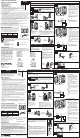
Installation
For installations involving more than one control in a wallbox, refer to Multi-
Unit Installations before beginning.
ON
OFF
ON
OFF
ON
OFF
Turnscrewsto
loosen.
VerifyTypeofSwitch.
Tag
or
Different-coloredscrew
(Common)
Ground
(barecopperor
greenwire).
Ground(barecopperorgreenwire).
DisconnectSwitchWires.
Backwired:
Insertscrewdriver.
Pullwireout.
ScrewTerminals:
Turnscrewsto
loosen.
Single-Pole:
Insulated wires connected
to two screws of the same
color. Replace with a
single-pole Dimmer.
3-Way:
Insulated wires connected to three screws. One of
these wires is connected to a screw of a different-col-
or or is labeled COMMON. Mark or Tag wire to identify
when rewiring. Replace the switch directly connected
to the load with the 3-way Dimmer.
or
RestorePower.
MountandAlignControl.InstallWallplate.
ImportantWiringInformation
Tighten
connectors.
Besurenobare
wireisexposed.
When making wire connections,
follow the recommended strip lengths
and combinations for the supplied
wire connectors.
Note:Wire connectors provided are
suitablefor copperwireonly.For
aluminum wire, consult an electrician.
Small
Large
Small:
Strip insulation 3/8 in (10 mm) for 14 AWG
(1.5 mm
2
) wire.
Strip insulation 1/2 in (13 mm) for 16 AWG
(1.0 mm
2
)
or 18 AWG (0.75 mm
2
) wire.
Use to join one 14 AWG (1.5 mm
2
) supply wire
with one 16 AWG (1.0 mm
2
)
or 18 AWG
(0.75 mm
2
) control wire.
Large:
Strip insulation 1/2 in (13 mm) for 10 AWG
(6 mm
2
), 12 AWG (2.5 mm
2
), or 14 AWG
(1.5 mm
2
)
wire.
Strip insulation 5/8 in (16 mm) for 16 AWG
(1.0 mm
2
) or 18 AWG (0.75 mm
2
) wire.
Use to join one or two 12 AWG (2.5 mm
2
)
or
14 AWG (1.5 mm
2
) supply wires with one
10 AWG (6 mm
2
), 12 AWG (2.5 mm
2
), 14 AWG
(1.5 mm
2
), 16 AWG (1.0 mm
2
), or 18 AWG
(0.75 mm
2
) control wire.
TurnPowerOFFatCircuitBreakerorRemoveFuse.
Startscrews.
Aligncontrolandtighten
screws.
ForaSingle-PoleCircuit:
• ConnectthegreenDimmer ground wire
to the bare copper or green ground wire
in the wallbox (see Important Note 4).
• ConnecttheredDimmer wire to the
wire leading to the circuit breaker or
fuse box.
• ConnecttheyellowDimmer wire to the
wire leading to the load.
• ConnectthewhiteDimmer wire to
neutral.
• Twist a wire connector onto the red/
white Dimmer wire. This wire is not
used in a single pole circuit.
Fora3-WayCircuit:
• A3-wayswitchmustbeonthelineside
of the Dimmer.
• Dimmermustbeonloadside.
See diagram.
• ConnectthegreenDimmer ground wire
to the bare copper or green ground wire
in the wallbox (see Important Note 4).
• ConnecttheredDimmerwire to one of
the wires leading to the 3-way switch.
• Connectthered/white Dimmer wire
to the other wire leading to the 3-way
switch.
• ConnecttheyellowDimmer wire to
the wire leading to the load (marked or
tagged wire).
• ConnectthewhiteDimmer wire to neutral.
WiringtheDimmer.
Green
Ground
Yellow
Red
White
Red/
White
Green
Ground
Yellow
Red
White
Red/
White
Tag
Red
Dimmer
Red/White
Green
Yellow
Ground
White
Load
Neutral
Live
120V~
60Hz
1
2
3
4
5
6
7
Notes:
1. If the red and yellow wires are
reversed, the lamp may flicker.
2. Connect the Dimmer to the load.
Notes:
1. If the red and yellow wires are
reversed, the lamp may flicker.
2. Connect the Dimmer to the load.
WARNING: Shock Hazard. May result in serious
injury or death. Turnoffpoweratcircuit
breakerbeforeinstallingtheunit.
RemoveWallplateandSwitchMountingScrews.PullSwitch
fromWallbutDONOTRemoveWires.
Lightlytighten
thescrews
120V~
60Hz
3-WaySwitch
Red
Red/White
Green
Yellow
Ground
White
Load
Neutral
Live
Dimmer
Tag
Lutron Electronics Co., Inc.
7200 Suter Road
Coopersburg, PA 18036-1299, U.S.A.
Hecho e impreso en E.U.A. 04/2011 P/N 030-1543 Rev. A
AtenuadordeLuzUnipolar/Tres
VíasElectrónicosdeBajoVoltaje
Clasificadopara120V~60Hz
Adquieralaplacadeparedporseparado.
NotasImportantes
Favordeleerantesdeinstalar.
1. PRECAUCIÓN:Para evitar un recalientamiento o el posible daño a otros equipos, no instale
para controlar iluminación de bajo voltaje suministrado por transformadores magnéticos,
receptáculos, accesorios fluorescentes, equipos motorizados, o equipos subministrados
por transformadores.
2. Use solamente para controlar el lado primario de luces de bajo voltaje subministrados
por transformadores electrónicos, o en combinación de luces incandescentes.
3. Este producto necesita un alambre neutro en la caja de embutir. Si no existe un alambre
neutro, llame a un electricista calificado para la instalación.
4.
Cuando no hay “medios de conexión a tierra” dentro de la caja de pared para un interruptor
o atenuador existentes, el 2011 National Electrical CodeR (NECR Código eléctrico nacional)
permite la instalación de un atenuador como reemplazo en tanto 1) se utilice una carátula
no combustible con tornillos de anexión no metálicos o 2) el circuito se proteja a través de
un interruptor de circuitos de falla de tierra. El NECR de 2008 proporciona los mismos
permisos, aunque no incluye el requisito de tornillos de anexión no metálicos. Cuando
instale un atenuador siguiendo cualquiera de estos métodos, cubra o retire el cable verde
antes de atornillar el atenuador en la caja de pared.
5. Algunos fabricantes no recomiendan la atenuación de transformadores de estado sólido. Para
determinar si un accesorio puede ser atenuado, consulte el fabricante del accesorio.
6. Este control está protejido contra sobre cargas. Si se excede el vatiaje clasificado, la
corriente al circuito se apagará hasta que el control se enfríe. Si esto ocurre, remueva la
carga excesa del circuito.
7. Durante la operación normal, el atenuador puede estar tibio at tacto.
8. En aplicaciones de fases múltiples, use un neutral en cada fase conteniendo un circuito
atenuado.
9. Para instalaciones nuevas, instale un interruptor de ensayo antes de instalar el atenuador.
10.Instale de acuerdo con los códigos nacionales y locales gobernando la electricidad.
11. Limpie la unidad con un paño suave y húmedo únicamente. No use agentes químicos
de limpieza.
AsistenciaTécnica
Si tiene preguntas referente a la instalación o operación de este producto, llame al Centro de
Soporte Técnico de Lutron. Por favor suministre el numero exacto del modelo con su llamada.
1.800.523.9466 (E.U.A., Canadá, y el Caribe) +1.888.235.2910 (México)
+1.610.282.3800 (Otros países)
Fax +1.610.282.6311 Internet:www.lutron.com
GarantíaLimitada
(VálidosolamenteenlosE.U.A.,Canadá,PuertoRico,yelCaribe.)
Lutron reparará o reemplazará, a su criterio, cualquier unidad cuyos materiales o fabricación resulten defectuosos en el término de
un año después de la fecha de compra. Para obtener servicio de garantía, la unidad debe devolverse al lugar de compra o enviar,
con franqueo pago, a Lutron, 7200 Suter Road, Coopersburg, Pennsylvania 18036-1299.
ESTAGARANTÍASEOFRECEENLUGARDECUALQUIEROTRAGARANTÍAEXPRESA.LAGARANTÍAIMPLÍCITADE
COMERCIABILIDADESTÁLIMITADAAUNA—O,APARTIRDELAFECHADECOMPRA.ESTAGARANTÍANOCUBRELOS
COSTOSDEINSTALACIÓN,DESMONTAJENIREINSTALACIÓN.TAMPOCOCUBREDA—OSRESULTANTESDEUNUSOIMPROPIO
OABUSO,NIDA—OSDEBIDOSAUNAINSTALACIÓNOCONEXIÓNINCORRECTA.ESTAGARANTÍANOCUBREDA—OS
INCIDENTALESNIRESULTANTES.LAOBLIGACIÓNDELUTRONCONRESPECTOACUALQUIERRECLAMACIÓNPORDA—OS
RELACIONADOSCONLAFABRICACIÓN,VENTA,INSTALACIÓN,ENTREGA,USO,REPARACIÓNOREEMPLAZODELAUNIDAD,NO
SUPERARÁ,ENNINGÚNCASO,ELPRECIODECOMPRA.
Esta garantía otorga derechos legales específicos, pero se podría tener otros derechos, que varían de un estado a otro. Algunos
estados no permiten la exclusión o limitación de daños incidentales ni resultantes, ni limitaciones en la duración de una garantía
implícita, por lo cual es posible que las limitaciones mencionadas anteriormente no correspondan en ciertos casos.
Lutron es una marca registrada de Lutron Electronics Co., Inc. NEC es una marca registrada de National Fire Protection Association,
Quincy, Massachusetts. © 2011 Lutron Electronics Co., Inc.
Español
InstalacióndeUnidadesMúltiples
Cuando combine controles en la caja de embutir, elimine todas
las secciones laterales internas antes de conectar los alambres.
Vea el diagrama siguiente. Use un alicate para doblarlas cuida-
dosamente hasta que se despeguen. Repita este proceso para
cada sección que necesite eliminar. Reducción de la capacidad
del atenuador se requiere en esta instalación. Use la tabla
siguiente para determinar la máxima capacidad del atenuador.
600W
LXELV-603PL
300W
DLELV-303PL
DVELV-303P
DVSCELV-303P
LGELV-303P
LTELV-303P
SELV-303P
CTELV-303P
Modelos:
SinEliminar UnaSección DosSecciones
Secciones Eliminada Eliminadas
300 W 250 W 200 W
600 W 500 W 400 W
Etiqueta
Delevueltas
altornillopara
soltarlo.
Instalación
Para instalaciones múltiples en una caja de embutir, antes de empezar vea las
instrucciones de unidades múltiples.
O
O
ON
OFF
ON
OFF
ON
OFF
Tornillodediferentecolor
(Common)
TerminalesdeTornillos:
Delevueltasaltornillo
parasoltarlo.
Tierra
(alambredecobre
desnudooverde)
Tierra
(alambredecobredesnudo
overde)
Unipolar:
Alambres revestidos están
conectados a dos tornillos del
mismo color. Reemplaze con un
atenuador Unipolar.
TresVías:
Alambres revestidos conectados a tres tornillos.
Uno de estos alambres está conectado a un
tornillo de diferente color o rotulado COMMON.
Marque o aplique una etiquetaa este alambre
para identificarlo. Reemplaze con un atenuador
de Tres Vías.
Desconectelosalambresdelinterruptor.
Verifiqueeltipodeinterruptor.
Retirelaplacadelapared.Tiredelosinterruptoresdelapared,
peronoquiteloscables.
Apaguelacorrienteenlacajadecircuitosoremuevalosfusibles.
Enciendalacorriente.
Monteyalinieelcontrol.Instalelaplacadepared.
ConexionesPosteriores:
Coloqueeldestornillador.
Saqueelalambre.
Conecteelcontrol.
Tuerza el conectador
de alambre hasta
que este firme.
Asegúrese que no
queden alambres
expuestos.
Cuando se conecten cables, la longitud expuesta de los extremos y la combi-
nación de conexiones deberán estar de acuerdo con las recomendaciones para
el conector suministrado. Nota: Los conectores suministrados son apropiados
para alambresdecobreúnicamente.Consulte a un electricista en caso de
usar conductores de aluminio.
Coloquelostornillos.
Alinieelcontroly
aprietelostornillos.
Verde
Tierra
Amarillo
Rojo
Blanco
Rojo/
Blanco
Rojo/
Blanco
Verde
Amarillo
Atenuador
Tierra
Blanco
Carga
Neutro
Vivo
Rojo
120V~
60Hz
EnuncircuitodeTresVias:
• Aseguresequeelinterruptordetresvías
esté conectado con el alambre vivo de la
línea.
• Elatenuadordebeinstalarsedelladode
la carga. Consulte la diagrama.
• Conecteelalambredetierraverdedel
control al alambre de tierra cobre
descubierto o de verde en la caja de
embutir (vea Notas Importantes 4).
• Conecteelalambrerojodel control a
uno de los alambres del interruptor de
tres vías.
• Conecteelalambrecolorrojoyblanco
del control al otro alambre del interruptor
de tres vías.
• Conecteelalambreamarillodel control
al alambre de la carga (alambre marcado
o etiquetado).
• Conecteelalambreblancodel control a
neutral.
EnuncircuitoUnipolar:
• Conecteelalambredetierraverde
del control al alambre de tierra cobre
descubierto o de verde en la caja de
embutir (vea Notas Importantes 4).
• Conecteelalambrerojodel control
al alambre que va a la caja de circuitos
o caja de fusibles.
• Conecteelalambreamarillodel control
al alambre que va a la carga.
• Conecteelalambreblancodel control
al neutral.
• Usandoconectadoresdealambres,cubra
el alambre color rojo/blanco del control.
Este alambre no se usa en circuitos
unipolares.
Instruccionesimportantesdecableado
Pequeño
Grande
1
2
3
4
5
6
7
Centro de Soporte Técnico de Lutron +1.888.235.2910 24 horas / 7 días www.lutron.com
Notas:
1. El control puede causar parpadeo en las
lamparas si se invierten los alambres rojo
y amarillo.
2. Conecte el control al alambre con la
carga.
Notas:
1. El control puede causar parpadeo en las
lamparas si se invierten los alambres rojo y
amarillo.
2. Conecte el control al alambre con la carga.
ADVERTENCIA: Peligro de choque eléctrico. Podría
resultar en lesiones graves o la muerte. Desconecte
laalimentacióneneldisyuntorantesdeinstalarla
unidad.
Pequeño:
Alambres de 1,5 mm
2
(14 AWG) quite la aislación en 10 mm
(3/8 pulgada) del extremo. Alambres de 1,0 mm
2
(16 AWG) ó 0,75 mm
2
(18 AWG) quite la aislación en 13 mm (1/2 pulgada) del extremo. Úselos
para conectar un cable de suministro de 1,5 mm
2
(14 AWG) con un cable
de control de 1,0 mm
2
(16 AWG) ó 0,75 mm
2
(18 AWG).
Grande:
Alambres de 6 mm
2
(10 AWG), 2,5 mm
2
(12 AWG) ó 1,5 mm
2
(14 AWG)
quite la aislación en 13 mm (1/2 pulgada) del extremo. Alambres de
1,0 mm
2
(16 AWG) ó 0,75 mm
2
(18 AWG) quite la aislación en 16 mm
(5/8 pulgada) del extremo. Úselos para conectar uno o dos cables de
suministro de 2,5 mm
2
(12 AWG) ó 1,5 mm
2
(14 AWG) con un cable de
control de 6 mm
2
(10 AWG), 2,5 mm
2
(12 AWG), 1,5 mm
2
(14 AWG),
1,0 mm
2
(16 AWG) ó 0,75 mm
2
(18 AWG).
Verde
Tierra
Amarillo
Rojo
Blanco
Rojo/
Blanco
Etiqueta
Aprieteligeramente
lostornillos
Noeliminelasseccioneslaterales
éxternas.
Eliminetodaslasseccioneslaterales
internas(sombreadas).
Atenuador
Etiqueta
Interruptorde
tresvías
Rojo
Rojo/
Blanco
Verde
Amarillo
Tierra
Blanco
Carga
Neutro
Vivo
120V~
60Hz