
Cut Sheet


RF Local Controls
®
SPECIFICATION SUBMITTAL Page
Job Name:
Job Number:
Model Numbers:
Maestro Wireless® Designer-style: Maestro®
369143m 11 03.04.14
1
When using controls in single location installations, tighten the blue terminal without any wires attached. Do not connect the blue terminal to any other wiring
or to ground.
2
Up to nine Maestro® Companion Dimmers / Switches may be connected to the Maestro Wireless® Dimmer / Switch. Total blue terminal wire length may be up
to 250 ft (76 m).
3
Neutral-wire Dimmers / Switches must be connected on the Load side of a multi-location installation.
Wiring Diagrams (continued)
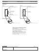
Multi-Location Dimmer/Switch Installation with Neutral
2,3
MRF2-6ND-120, -6ELV-120 with MA-R/MSC-AD; -6ANS, -8ANS-120 with MA-AS/MSC-AS
Companion
Dimmer/Switch
Companion
Dimmer/Switch Dimmer/Switch
Brass
Silver
BrassBrass
BlackBlackBlack
Hot/Live
GreenGreenGreen
BlueBlueBlue
GroundGroundGround
Neutral
120 V~ 60 Hz
Load
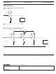
Single-Location Dimmer/Switch Installation with Neutral
MRF2-6ND-120, -6ELV-120, -6ANS, -8ANS-120
Dimmer/Switch
Load
Brass
Black
Silver
Hot/Live
Green
Blue
1
Ground
Neutral
120 V~ 60 Hz