
Cut Sheet

RF Local Controls
®
SPECIFICATION SUBMITTAL Page
Job Name:
Job Number:
Model Numbers:
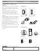
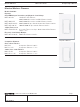
Maestro Wireless® Designer-style: Maestro®
369143m 6 03.04.14
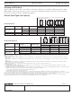
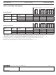
Switch Load Type and Capacity
Neutral Required
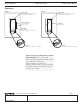
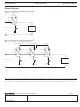
Do not remove outside fins on ends of ganged controls
(shaded areas below)
A B B B C B
Control Voltage Load Type Minimum Load
Maximum Load
A: Not Ganged B: End of Gang C: Middle of Gang
MRF2-8ANS-120
1,2
120 V~
Lighting 25 W 8 A 6.5 A 5 A
Fan Motor 0.2 A 1/4 HP (5.8 A) 1/4 HP (5.8 A) 1/6 HP (4.4 A)
MRF2-6ANS
1
120 V~
Lighting 25 W 6 A 5 A 3.5 A
Fan Motor 0.2 A 1/10 HP (3 A) 1/10 HP (3 A) 1/10 HP (3 A)
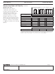
No Neutral Required
A B B B C B
Control Voltage Load Type Minimum Load
Maximum Load
A: Not Ganged B: End of Gang C: Middle of Gang
MRF2-8S-DV
1
120 – 277 V~ Incandescent/Halogen 25 W 8 A 8 A / 7 A
4
7 A
120 – 277 V~ Fluorescent/LED/CFL 40 W (LUT-MLC)
3
8 A 8 A / 7 A
4
7 A
120 V~ Fan Motor 0.4 A 1/10 HP (3 A) 1/10 HP (3 A) 1/10 HP (3 A)
1
Switch Load Type:
• MRF2-8ANS-120 is designed for use with permanently-installed lighting loads and with fan motor loads up to 1/4 HP (5.8 A).
• MRF2-6ANS is designed for use with permanently-installed lighting loads and with fan motor loads up to 1/10 HP (3 A).
• MRF2-8S-DV is designed for use with permanently-installed lighting loads and with fan motor loads up to 1/10 HP (3 A, 120 V~ only).
2
For loads larger than 8 A (120 V~), the MRF2-8ANS-120 switch can be used with the PHPM-SW-DV-WH power booster.
3
The LUT-MLC ensures proper function with certain fluorescent, CFL, and LED load types.
4
Maximum load for double-gang application is 8 A. Triple-gang application derates maximum load to 7 A.