
Cut Sheet


Maestro® Sensor
369666c 12 09.11.12
®
SPECIFICATION SUBMITTAL Page
Job Name:
Job Number:
Model Numbers:
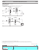
Switch with Occupancy/ Vacancy Sensor
Single Location Installation (120-277 V~)
1, 2
-OPS6M2N-DV,-VPS6M2N-DV
Wiring Diagram 7
Occupancy
sensing switch
120-277V~
50/60Hz
White
Ground
Hot/Live
Neutral
Load
Blue
1
Bare
Black Black
1
Whenusingcontrolsinsinglelocationinstallations,tightentheblueterminalorcapbluewire.DoNOTconnecttheblueterminal/wiretoanyotherwireortoground.
2
Fanloadappliesto120V~only(notfor277V~).
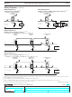
3
OnlyoneOccupancysensingswitchcanbeusedpermulti-locationcircuit.
4
Asinglestandardmechanical3-wayswitchorupto9companionswitchesmaybeconnectedtomostOccupancysensingswitches.
Standardmechanical3-wayswitchcannotbecombinedwithcompanionswitch.Totalblueterminalwirelengthmaybeupto150ft(46m).
Wiring Diagrams (continued)
Continued on next page...
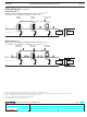
3-way Installation with Standard Mechanical Switch (120 V~)
3, 4
-OPS6M2N-DV,-VPS6M2N-DV
Wiring Diagram 8
OR
Black
Blue
Ground
Occupancy
sensing switch
White
Ground
120V~
50/60Hz
Hot/Live
Neutral
Load
Standard
mechanical switch
Black
Jumper wire
Bare
Different
color screw
(Common)
Green
screw
Black
Blue
White
Ground
Occupancy sensing
switch
Ground
120V~
50/60Hz
Hot/Live
Neutral
Load
Standard
mechanical switch
Black
Jumper wire
Bare
Different
color screw
(Common)
Green
screw
12