
Cut Sheet


®
SPECIFICATION SUBMITTAL Page
Job Name:
Job Number:
Model Numbers:
Maestro® Maestro 0–10 V Dimmer Sensor Sensor
369833a 10 08.27.14
m30
15
5
1
Occ
LRN
Fixd
Vac
Mode
Hi
Med
Low
Off
Hi
Med
Low
Min
PIR
m30
15
5
1
Hi
Med
Low
Off
Occ
Lrn
Fixd
Vac
Mode
Hi
Med
Low
Min
PIR
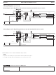
Traditional 3-Way Mechanical Switch Wiring
Ground
Traveler Traveler
Common
m30
15
5
1
Occ
LRN
Fixd
Vac
Mode
Hi
Med
Low
Off
Hi
Med
Low
Min
PIR
m30
15
5
1
Hi
Med
Low
Off
Occ
Lrn
Fixd
Vac
Mode
Hi
Med
Low
Min
PIR
Yellow Jumper
wire (included)
Traveler (to Blue wire)
Tagged Wire
(Common)
Traveler
(to Black wire)
Ground
Different color
screw
3-Way Mechanical Switch Wiring with Dimmer Sensor
Different color
screw
Rewire to
3-Way Retrofit Installation
For retrofit 3-way installations the mechanical switch needs to be rewired as shown in the diagram below after wiring the dimmer
sensor. Otherwise, the 3-way installation will not work as expected. Single pole mechanical switches may also be used in a 3-way
installation with MS-Z101 and MS-Z101-V models.
1. Connect Ground: Ensure the bare copper or green ground wire from the wallbox is connected to the green ground screw of the
mechanical switch.
2. Tag circuit Common: Your 3-way mechanical switch should have three screw terminals, two of the same color, and one of a different
color. Tag the wire that is connected to the screw terminal of a different color.
3. Identify the wire that matches the color of the wire you connected to the blue wire of the MaestroR Dimmer Sensor. Connect this wire to
one of the two terminals of the same color.
4. Combine the tagged wire, the remaining wire and yellow jumper wire (included) using a wire connector. Connect the other end of
jumper wire to the different color screw.