
Cut Sheet


®
SPECIFICATION SUBMITTAL Page
Job Name:
Job Number:
Model Numbers:
Maestro® Maestro 0–10 V Dimmer Sensor Sensor
369833a 3 08.27.14
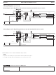
Load Type and Capacity
Control
Neutral
Connection
Vacancy
Only
0-10 V-
Current
3,4
Voltage / Load Type /
Maximum Load
(Anywhere in Gang)
1
Minimum
Load
3-Way with
Mechanical
Switch
Multi-Location
with Accessory
Switch
MS-Z101- Optional
50 mA
max sink
120–277V~
Electronic fluorescent ballast or LED
drivers, 8 A
120V~
Fan 4.4 A (1/6 HP)
2
0 A
MS-Z101-V Optional
50mA
max sink
0 A
1
Dimmer sensor load type: Designed for use with permanently installed electronic fluorescent ballast or LED driver lighting loads. Do not install dimmers to
control receptacles or motor-operated appliances.
2
When controlling light and fan loads simultaneously on a single-circuit, maximum load capacity per circuit is 4.4 A at 120 V~.
3
The length of the 0–10 V - control wires are not to exceed 250 ft (76.2 m) of wire having a size no less than 20 AWG (0.75 mm
2
).
4
The 0–10 V - wires must be installed as Class One per NEC or local jurisdiction.
NOTES:
– Ground or neutral is required for product to function. If neither is present, consult a licensed electrician.
– When power is applied, the dimmer sensor can be manually turned on or off after the first 10seconds and will automatically control the load after 2minutes.
– Works with all ballasts and drivers that provide a current source compliant to IEC 60929 Annex E.2.