
Cut Sheet


®
SPECIFICATION SUBMITTAL Page
Job Name:
Job Number:
Model Numbers:
Maestro® Maestro 0–10 V Dimmer Sensor Sensor
369833a 6 08.27.14
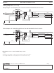
Horizontal Beam Diagram
(For Reference Only)
5 ft
(1.5 m)
5 ft
(1.5 m)
0
10 ft
(3 m)
10 ft
(3 m)
15 ft
(4.5 m)
15 ft
(4.5 m)
20 ft
(6 m)
20 ft
(6 m)
25 ft
(7.5 m)
25 ft
(7.5 m)
30 ft
(9 m)
30 ft
(9 m)
Vertical Beam Diagram
0
10 ft
(3 m)
15 ft
(4.5 m)
20 ft
(6 m)
25 ft
(7.5 m)
30 ft
(9 m)
NEMA WD7 Test Grid Coverage (High Sensitivity Setting)
5 ft
(1.5 m)
5 ft
(1.5 m)
0
10 ft
(3 m)
10 ft
(3 m)
15 ft
(4.5 m)
15 ft
(4.5 m)
5 ft
(1.5 m)
Major motion coverage: 900 ft( (81 m()
Minor motion coverage: 400 ft( (36 m()
MaestroR 0–10 V Dimmer Sensor Placement and Operation
• The ability of the dimmer sensor to detect motion requires line-of-sight of room occupants. The dimmer sensor
must have an unobstructed view of the room.
• Hot objects and moving air currents can affect the performance of the dimmer sensor. For best performance, the
dimmer sensor should be mounted at least 4 ft (1.2 m) away from HVAC vents and light bulbs.
• The performance of the dimmer sensor depends on a temperature differential between the ambient room temperature
and that of room occupants. Warmer rooms may reduce the ability of the dimmer sensor to detect occupants.
10 ft
(3 m)
20 ft
(6 m)
30 ft
(9 m)
4 ft
(1.2 m)
0