
Cut Sheet


®
SPECIFICATION SUBMITTAL Page
Job Name:
Job Number:
Model Numbers:
Maestro® Maestro 0–10 V Dimmer Sensor Sensor
369833a 8 08.27.14
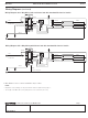
Wiring Diagrams
Wiring Diagram 1A: Single Pole Wiring without Neutral
m30
15
5
1
Occ
Lrn
Fixd
Vac
Mode
Hi
Med
Low
Min
PIR
120 – 277 V ~
50 / 60 Hz
8 A
Alt
TURN OFF POWER
ARRETEZ LE COURANT
DESCONECT LA CORRIENTE
Up
Coopersburg, PA
800.523.9466
lutron.com
Neutral
Black
Black
Green
Green/Yellow
Ground
Line
120–277 V~
50 / 60 Hz
Purple (+)
Purple (+)
Gray (–)
Gray (–)
Black
Black
White
White
Purple (+)
Gray (–)
Blue
m30
15
5
1
Occ
Lrn
Fixd
Vac
Mode
Hi
Med
Low
Min
PIR
120 – 277 V ~
50 / 60 Hz
8 A
Alt
TURN OFF POWER
ARRETEZ LE COURANT
DESCONECT LA CORRIENTE
Up
Coopersburg, PA
800.523.9466
lutron.com
Wiring Diagram 1B: Single Pole Wiring with Neutral
Neutral
Black
Black
Green
Ground
Line
120–277 V~
50 / 60 Hz
Purple (+)
Purple (+)
Gray (–)
Gray (–)
Black
Black
White
White
Purple (+)
Gray (–)
Blue
White*
See note below
Wiring Diagrams with Neutral:
MS-Z101 and MS-Z101-V must
have the green/yellow wire
connected to ground to function,
or the white sleeve can be placed
over the green/yellow wire then
connected to neutral.
m30
15
5
1
Occ
Lrn
Fixd
Vac
Mode
Hi
Med
Low
Min
PIR
120 – 277 V~
50 / 60 Hz
8 A
Alt
TURN OFF POWER
ARRETEZ LE COURANT
DESCONECT LA CORRIENTE
Up
Coopersburg, PA
800.523.9466
lutron.com
Green/Yellow wire covered by white
sleeve connects to neutral
Green/Yellow wire
connects to ground
NOTES:
– When using controls in single location installations, cap the blue wire. Do not connect the blue wire to any other wiring or to ground.
• Before installing wallplate, program all desired settings.
*