
Installation Manual

2
Multi-gang Installation
In multi-gang installations several dimmers or controls are
grouped horizontally in one ganged switchbox or in a
series of interconnected switchboxes. Multi-gang
faceplates are available to simplify and improve the
appearance of these installations. A multi-gang mounting
frame is provided with each standard multi-gang faceplate
to ensure proper alignment of dimmers, easy application of
the faceplate, and a flat surface for the installation. This
frame is most easily mounted on the wall before dimmer
wires are connected. Refer to multi-gang instruction sheet
supplied with multigang faceplate.
No Side Sections Removed
(No Derating Required)
Installation of dimmers without removing side sections
allows operation at full capacity (i.e., no derating is
required). Follow instructions below. For retrofit
installations, side sections can be removed to fit existing
switchboxes. See Multi-gang Installation, "Side Sections
Removed" at right.
1. Assure safe operation by using Ballast Chart (Figure
A) to determine maximum number of lamps safely used
with specific ballast. Note: Use ONLY dimming ballasts
listed on chart. Do not use any other ballasts.
2. Determine the number of switchboxes necessary by
using Switchbox Requirement Chart in Figure B. When
ganging any combination of "small" (NF-10, NF-10-277)
and "large" (NF-20, NF-30, NF-20-277) dimmers, place all
small dimmers at one end of the gang and all large
dimmers at the other end.
3. When ganging an EVEN number of SMALL dimmers,
use gangable switchboxes with tapped ears as shown
below. Do not use plaster rings or gangbox covers. Space
an "additional" switchbox
3
/4" apart from the other
switchbox(es). A
3
/4" chase nipple is recommended as a
spacer between the switchboxes. (Example, 4 small
dimmers require 5 switchboxes. See Figure C.)
4. Wire each dimmer according to Steps in "Single Unit
Installation" on page 3.
5. Install dimmers in switchbox(es). When combining
small and large dimmers, place all small dimmers on one
extreme end of the gang, and large dimmers at the other
end of the gang. Use center and offset mounting holes as
required for proper alignment. Allow
1
/32" between dimmers
for ease in attaching faceplate. See Figure D.
6. Replace sliders and snap on multi-gang faceplate (or
multiple single faceplates) and adjust up or down for a
snug fit. Multi-gang faceplates (with mounting frames and
instructions) are available in a variety of colors to beautify
and simplify your installation.
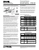
Number of Small Controls (NF-10)
0123456
Number 0 0 1 1+1* 4 4+1* 7 7+1*
of Large 113568911
Controls 24679101213
(NF-20, 3 6 8 10 11 13 14 16
NF-30) 4 9 11 12 14 15 17 18
* See Item 3
Figure B: Switchbox Requirement Chart
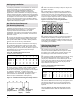
No Side Sections Removed
Four-gang
gangable wallbox
Single-gang
gangable
wallbox
3
/4" space
(use chase
nipple)
Figure D: Front View - Four-Gang Installation
No Side Sections Removed
Offset Mounting Holes
Center Mounting Holes
1
/32" Spacing
Side Sections Removed
(Derating Required)
1. Derating is necessary when side sections are
removed. Use Derating Ballast Chart in Figure A. Match
the dimmer size, number of side sections removed, and
the ballast type to determine maximum safe load.
2. Determine number of switchboxes necessary by using
the Switchbox Requirement Chart in Figure E. When
ganging any combination of "small" dimmers (NF-10, NF-
10-277) and "large" (NF-20, NF-30, NF-20-277) dimmers,
place all small dimmers at one end of the gang and all
large dimmers at the other end.
3. Remove INNER side sections only. Using pliers, bend
side sections down as far as you can and then back to
their original positions. Side sections will break off. See
Figure E.
DO NOT REMOVE OUTER SIDE SECTIONS OF THE
TWO DIMMERS WHICH ARE ON THE ENDS OF THE
GANG.
Number of Small Controls (NF-10)
0123456
Number 0 0123456
of Large 1 1345678
Controls 2 35678910
(NF-20, 3 5789101112
NF-30) 4 7 9 10 11 12 13 14
Figure E: Switchbox Requirement Chart
Side Sections Removed
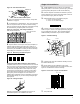
Figure C: Switchbox Positioning Four-Gang Controls