
Installation Manual

3
Single Unit Installation
1. TURN POWER OFF at fuse box or circuit breaker.
Wiring with power on can result in personal injury. Damage
caused by wiring with power on will void the warranty.
2. Remove faceplate and slider from dimmer to prevent
surface damage and to access mounting holes. Pull out at
top and bottom edges, plate will snap off.
3. Strip switchbox wires to the following lengths:
5
/8" for No. 16 and 18 gauge
1
/2" for No. 10, 12, and 14 gauge
4. Use wire connectors supplied to make the connections
shown in Figure I. Refer to the appropriate wiring diagram
for your application on page 4, when installing dimmer.
Additional wiring information may be found on ballast.
5. Carefully push wires into switchbox allowing room for
the dimmer's backcover.
6. Mount dimmer into the switchbox using center
mounting holes in dimmer base and screws provided. See
Figure K. Unit MUST be mounted vertically.
7. Turn power ON.
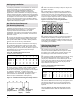
Figure E: Side Section Removal
1/2" or 5/8"
Side section break-off points
4. Wire each dimmer according to Steps in "Single Unit
Installation" on page 3.
5. Install dimmers in switchbox(es). Use center mounting
holes as required for first unit, then use offset mounting
holes as required for proper alignment. Remember to keep
all small dimmers grouped together. See Figure F.
6. Replace sliders and snap on multi-gang faceplate (or
multiple single faceplates) and adjust up or down for a
snug fit. Multi-gang faceplates (with mounting frames and
instructions) are available in a variety of colors to beautify
and simplify your installation. See Figure G.
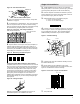
Figure F: Front View - Four-Gang Installation
Side Sections Removed
Inner Side Sections
Removed
Multigang faceplates, which eliminate the need to cut
individual faceplates, are available from Lutron.
Center Mounting Holes
Figure H: Cutting Faceplate
Cutting Faceplates When Removing Side Sections:
Faceplates will need to be cut if side sections are removed
when not using a multi-gang faceplate. Place faceplate on
a soft cloth face down. Press firmly and score the groove
on the back of faceplate with a razor sharp knife, using
vertical groove to keep knife on a straight course. Bend
section back and forth to break it off. Smooth edges by
placing fine-grained sandpaper on a flat surface and
rubbing edge of faceplate over the sandpaper a few times.
Hold faceplate steady as you rub to keep a straight edge.
See Figure H.
Figure G: Multi-Gang Unit With Faceplate
Offset Mounting Holes
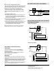
Figure I: Switchbox Wiring
Yellow
Red
White
Control
Switch Hot
Neutral
Ground
Hot
Black
Green or Bare
To
Ballasts
To Fuse Box or
Curcuit Breaker
Figure K: Front View - Single Unit Installation
Trimpot Shaft
Offset Mounting Holes Center Mounting Holes