
Information Sheet

®
SPECIFICATION SUBMITTAL Page
Job Name:
Job Number:
Model Numbers:
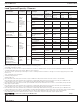
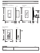
Caséta Wireless Load Controls
369987g 10 06.28.19
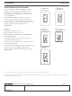
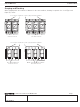
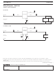
Wiring Diagrams - Switches
1
When using controls without a mechanical 3-way switch, cap the blue terminal. Do not connect the blue wire to any other wiring or to ground.
2
A LUT-MLC ensures proper function when LED, fluorescent, or ELV loads are used. Install the LUT-MLC inside a load fixture or in a separate junction box
within the circuit.
3
The red wire must be connected to the load and the black wire must be connected to Line / Hot. The switch will not work if the wires are reversed.
Single Location Installation
PD-5WS-DV
PD-5ANS, PD-6ANS
PD-5WS-DV
PD-5ANS or
PD-6ANS
LUT-MLC
2
Load
Load
Line / Hot
Line / Hot
Neutral
Neutral
Green
Green
Ground
Ground
Black
Black
Black
Red
3
Blue
1
Blue
1
120 / 277 V~
50 / 60 Hz
120 V~
50 / 60 Hz
(continued on next page…)
White