
Cut Sheet


Lutron®
|
9www.lutron.com/radiora2
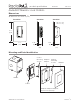
product specifications
01.21.11
369-225f
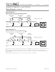
Multi-Location 2-wire Switch Installation
3
(120 V )
-8S-DV with RD-RS and optional shunt capacitor
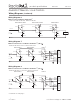
Multi-Location 2-wire Switch Installation
3
(277 V )
-8S-DV with RD-RS-277 and optional shunt capacitor
1
When using controls in single location installations, tighten the blue terminal. Do not connect the blue terminal to any other wiring or to ground.
2
Optional shunt capacitor must be installed inside the load fixture or in a separate J-box. Shunt capacitor is included with -8S-DV.
3
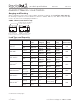
Up to 9 RadioRA 2 Remote Dimmers / Switches may be connected to the RadioRA 2 Dimmer / Switch. Total blue terminal wire length may be
up to 250 ft (76 m).
4
Neutral wire Dimmers / Switches must be connected on the Load side of a multi-location installation.
Switch or
Remote Switch
120 V
50 / 60 Hz
Brass
Black
Green
Ground
Hot/Live
Neutral
Load
Blue
Shunt
Capacitor
2
Optional
Brass
Black
Green
Ground
Blue
Brass
Black
Green
Ground
Blue
Note: Switch can be installed
in any location in the circuit.
Remote Switch
or Switch
Remote Switch
or Switch
Switch or
Remote Switch
277 V
50 / 60 Hz
Brass/
Red
Black
Green
Ground
Hot/Live
Neutral
Load
Blue
Shunt
Capacitor
2
Optional
Black
Green
Ground
Blue
Red/
Brass
Black
Green
Ground
Blue
Remote Switch
or Switch
Remote Switch
or Switch
RadioRA 2 Maestro® Local Controls
Wiring Diagrams (continued)
Wiring Diagram 9
Wiring Diagram 10
Note: Switch can be installed
in any location in the circuit.
Red/
Brass