
Information Sheet

product specifications 369227f 02.19.14
2 Technical Support: 800.523.9466 (USA)
+44.(0)20.7702.0657 (Europe)
www.lutron.com
Model Numbers RR-MAIN-REP-WH, RR-MAIN-REP-WHBA, RR-AUX-REP-WH, RR-AUX-REP-WHBA,
RRK-MAIN-REP-WH, RRK-AUX-REP-WH
Power Main / Auxiliary Repeater: 9 V- 300 mA
See Low-Voltage Transformer spec (Lutron® P/N 369561)
Typical Power
Consumption
Main Repeater: 3.1 W
Test conditions: one LED on, Ethernet cable plugged in, powered by the 9 V- adapter
Auxiliary Repeater: 0.6 W
Test conditions: one LED on, powered by the 9 V- adapter
Regulatory
Approvals
Main / Aux (-WH only): cULus listed; FCC certified; Industry Canada certified; COFETEL
certified; ASEP certified; Bermuda Department of Telecommunications type approval; CRC
certified; INDOTEL certified; SUTEL certified
Main / Aux (-WHBA only): ANATEL certified
Main / Aux (RRK only): CE marked
Adapter (T120-9DC-3-BL): cULus listed; NOM certified
Environment Ambient operating temperature: 32 °F to 104 °F (0 °C to 40 °C), 0% to 90% humidity,
non-condensing. Indoor use only
Low-Voltage
Wire Type
Two pairs:
one pair 18 AWG (1.0 mm
2
),
one pair 22 AWG to 18 AWG (0.5 mm
2
to 1.0 mm
2
) twisted shielded –
IEC PELV/NEC®Class 2 cable
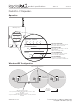
Communications Repeaters communicate with the system through RF. All devices must be located
within 30 ft (9 m) of a Repeater. All Repeaters must be within 60 ft (18 m) of another
Repeater. System devices operate on frequencies between 431.0 MHz to 437.0 MHz or
868.125MHz to 869.850 MHz
ESD Protection Tested to withstand electrostatic discharge without damage or memory loss, in accordance
with IEC 61000-4-2.
Surge Protection Tested to withstand surge voltages without damage or loss of operation, in accordance
with IEEE C62.41-1991 Recommended Practice on Surge Voltages in Low-Voltage AC
Power Circuits
Power Failure Power failure memory: should power be interrupted, the Repeater will return to its previous
state when power is restored
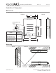
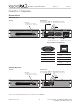
Mounting Mount on a wall, ceiling, or level surface using the two #6 (M3) screws provided
Connections Main Repeater: Ethernet, RS232 and RS485
Warranty www.lutron.com/TechnicalDocumentLibrary/Warranty.pdf
www.lutron.com/TechnicalDocumentLibrary/Intl_Warranty.pdf
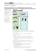
•
Test button: enters the system diagnostic mode.
•
Can be programmed from a PC.
•
RS485 port to connect to other Repeaters through a
wired link (daisy-chain).
•
Main
Repeaters allow configuration and integration to the
system through Ethernet or RS232 ports (see chart to
the right).
•
System with 2 Main Repeaters must be connected via Ethernet.
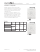
Design Features
RadioRA® 2 Repeaters
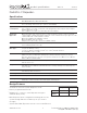
Specifications
Configuration Integration
Ethernet
P P
RS232
P