
Information Sheet


product specifications
02.10.20369225r
RadioRA 2 RF Maestro Local Controls
14
Customer Assistance:
1.844.LUTRON1 (U.S.A. / Canada)www.lutron.com/support
Continued on next page...
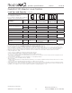
Wiring Diagrams (continued)
Wiring Diagram 6
Multi-Location Installation with Neutral
1,2
-10ND, -6ND, -6NA, -PRO, and -2ANF with RD-RD; -8ANS with RD-RS
Remote Dimmer
or Remote Switch
Remote Dimmer
or Remote Switch
Dimmer / Switch / Fan
Speed Control
2
Brass
Silver
BrassBrass
BlackBlackBlack
Line / Hot
GreenGreenGreen
BlueBlueBlue
GroundGroundGround
Neutral
120 V~
50 / 60 Hz
Load
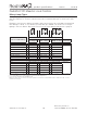
Wiring Diagram 5
Multi-Location Installation without Neutral
1
-6CL, -10D, and -PRO with RD-RD
Remote Dimmer
or Dimmer
Remote Dimmer
or Dimmer
Dimmer or
Remote Dimmer
BrassBrassBrass
BlackBlackBlack
Line / Hot
GreenGreenGreen
BlueBlueBlue
GroundGroundGround
Neutral
120 V~
50 / 60 Hz
Load
Note: Dimmer can be
installed in any location
in the circuit.
Note: Bolded lines in diagrams indicate leads on products.
1
Up to 9 Remote Dimmers / Remote Switches may be connected to the Dimmer / Switch / Fan Speed Controls. Total blue terminal wire
length may be up to 250 ft (76 m), except for -PRO which is 150 ft (45 m).
2
Neutral-Wire Dimmers / Switches / Fan Speed Controls must be connected on the Load side of a multi-location installation, except
-PRO which can be connected in any position.