
Cut Sheet

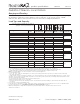


product specifications
01.15.15369225k
RadioRA® 2 Maestro® Local Controls
10 Technical Support — 800.523.9466 (USA)www.lutron.com
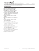
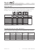
Wiring Diagrams
Continued on next page...
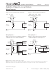
Wiring Diagram 1
Single-Location Installation without Neutral
1
-6CL, -6D, -10D
Dimmer
Load
Brass
Black
Hot/Live
Green
Blue
1
Ground
Neutral
120 V~
50/60 Hz
Wiring Diagram 4
Single-Location 2-Wire Switch Installation
1
-8S-DV with Optional Shunt Capacitor
2
Switch
Load
Shunt
Capacitor
2
Brass
Black
Hot/Live
Green
Optional
Blue
1
Ground
Neutral
120 –277 V~
50/60 Hz
Wiring Diagram 2
Single-Location Installation with Neutral
1
-10ND, -6NA, -2ANF, -8ANS
Dimmer/Switch/Fan Speed Control
Load
Brass
Black
Silver
Hot/Live
Green
Blue
1
Ground
Neutral
120 V~
50/60 Hz
Wiring Diagram 3
Single-Location Fluorescent Dimmer Installation
1
-F6AN-DV with Lutron® Ballast/LED Driver
Dimmer
Lutron®
Ballast/LED
Driver
Lutron®
Ballast/LED
Driver
Brass
Black
Silver
Hot/Live
Green
Orange
Orange
Orange
White
White
Black
Black
Blue
1
Ground
Neutral
120 –277 V~
50/60 Hz
Note: Bolded lines in diagrams indicate leads on products.
1
When using controls in single-location installations, tighten the blue terminal. Do not connect the blue terminal to any other wiring or to
ground.
2
Optional Shunt Capacitor must be installed inside the load fixture or in a separate J-box. Shunt capacitor is included with -8S-DV.