
Cut Sheet


product specifications
01.15.15369225k
RadioRA® 2 Maestro® Local Controls
7 Technical Support — 800.523.9466 (USA)www.lutron.com
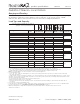
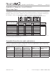
Load Type and Capacity (continued)
Do not remove outside fins on ends of
ganged controls (shaded areas).
Load Type
Minimum
Load
A
Not Ganged
B
End of Gang
C
Middle of Gang
Neutral
Connection
RRD-F6AN-DV
1,2,3
Fluorescent/LED Drivers
0.05 A 6 A 5 A 3.5 A
Yes
1 ballast 60 ballasts 50 ballasts 35 ballasts
RRD-2ANF
4
Ceiling Fan 0.083 A 2 A 2 A 2 A Yes
RRD-8ANS
1,5
Lighting 10 W 8 A 6.5 A 5 A
Yes
Motor 0.08 A 1/4 HP 5.8 A 1/4 HP 5.8 A 1/6 HP 4.4 A
RRD-8S-DV
5,6
Lighting 40 W/ VA 8 A
8 A (2-gang);
7 A (3-gang)
7 A
No
Motor 0.4 A 1/10 HP 3 A
Note: Do not install dimmers to control receptacles or motor-operated appliances.
1
Power Boosters / Load Interfaces: -F6AN-DV, -8ANS can be used to control power boosters / load interfaces. For a list of compatible power
boosters / load interfaces see Compatible Power Boosters and Load Interfaces, page 8.
2
Fluorescent Dimmer Load Type: -F6AN-DV: designed for use with permanently installed 3-wire 120 V~ or 277 V~ line voltage control
fluorescent ballasts or LED drivers. Use with only Hi-lume®, Hi-lume® 3D, Compact SETM, Eco-10®, or EcoSystem® (H3D-, FDB-, ECO-,
HL3-, EC5-, L3D). Do NOT use with any other ballasts or drivers. Do not install to control receptacles or motor-operated appliances.
3
Maximum Load: The maximum load for the -F6AN-DV is either the derated load or the number of ballasts, whichever is LESS.
4
Ceiling Fan Application: -2ANF
• Use to control one paddle-type ceiling fan (permanent split-capacitor).
• Use the ceiling fan’s pull chain to set its speed to the highest setting.
• Do not use to control fans that use shaded-pole motors (e.g., bath exhaust fans).
• Do not use to control fans that have integrated fan speed controls (e.g., fans that have a remote control) unless the integrated control is
removed from the ceiling fan.
• Do not connect to any other motor-operated appliance or to any lighting load type.
• Do not use to control a fan lighting load (e.g., light kit).
5
Switch Load Type:
• -8ANS, -8S-DV: designed for use with permanently installed 120 V~ incandescent, MLV, ELV, tungsten halogen, fluorescent, CFL, LED,
or motor loads.
• -8S-DV can also be used with permanently installed 277 V~ MLV or fluorescent loads.
6
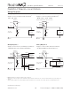
Shunt Capacitor: Some -8S-DV installations may require the use of a shunt capacitor; this is especially necessary for load types sensitive
to leakage current (e.g., fluorescent ballasts). If load flickers, install a shunt capacitor. Optional shunt capacitor must be installed inside the
load fixture or in a separate J-box. For shunt capacitor installation see Wiring Diagram 4, 9, or 10.
A B B B C B