
Installation Guide


Lutron Electronics Co., Inc.
7200 Suter Road
Coopersburg, PA 18036-1299, U.S.A.
Made and printed in U.S.A. 9/09 P/N 030-1110 Rev. A
P/N 030-1110
P/N 030-1110
P/N 030-1110
P/N 030-1110
120 V Halogen / Incandescent Dual Dimmer
S2-L, S2W-L
Rated at 120 V 60 Hz 600 W (300 W per circuit)
Important Notes
Please read before installing.
1. CAUTION: To avoid overheating and possible damage to other equipment, do not use to control
receptacles, fluorescent lighting fixtures, motor-operated or transformer-supplied appliances.
2. Dimmer requires separate wires in the wallbox for each light circuit.
3. When no "grounding means" exist within the wall box the NEC
© 2008, Article, 404.9 allows a
dimmer without a grounding connections to be installed as a replacement as long as a plastic,
noncombustible wallplate is used. For this type of installation, cap or remove the green ground
wire on the dimmer and use an appropriate wallplate such as the Lutron's Claro
® series
wallplates.
4. Do not use for lights switched from two locations (3-Way).
5. Use only with permanently installed 120 V~ halogen or incandescent fixtures.
6. Dimmer may feel warm to the touch during normal operation.
7. For new installations, wire a test switch before installing the control.
8. Install in accordance with all national and local electrical codes.
9. Clean dimmer with a soft damp cloth only. Do not use any chemical cleaners.
Multi-Unit Installations
When combining controls in a wallbox, remove all inner side sections before wiring (see below). Use
pliers to bend each side section up and down until it breaks off. Repeat for each side section to be
removed. Reduction of dimmer capacity is also required. Refer to chart below for maximum capacity.
Remove all inner side
sections (shaded).
Do not remove outer
side sections.
Model No Sides 1 Side 2 Sides
Number Load Removed Removed Removed
S2-L
Halogen / Incandescent 300 W / 300 W 250 W / 250 W 200 W / 200 W
Technical Assistance
If you have questions concerning the installation or operation of this product, call the Lutron Technical
Support Center. Please provide exact model number when calling.
1.800.523.9466 (U.S.A., Canada, and the Caribbean), for México, call +1.888.235.2910
Other countries call +1.610.282.3800
Fax +1.610.282.6311 Internet: www.lutron.com
Limited Warranty
(Valid only in the U.S.A., Canada, Puerto Rico, the Caribbean.)
Lutron will, at its option, repair or replace any unit that is defective in materials or manufacture within one year after purchase. For warranty
service, return unit to place of purchase or mail to Lutron at 7200 Suter Rd., Coopersburg, PA 18036-1299, postage pre-paid.
THIS WARRANTY IS IN LIEU OF ALL OTHER EXPRESS WARRANTIES, AND THE IMPLIED WARRANTY OF MERCHANTABILITY IS LIMITED
TO ONE YEAR FROM PURCHASE. THIS WARRANTY DOES NOT COVER THE COST OF INSTALLATION, REMOVAL OR REINSTALLATION,
OR DAMAGE RESULTING FROM MISUSE, ABUSE, OR DAMAGE FROM IMPROPER WIRING OR INSTALLATION. THIS WARRANTY DOES
NOT COVER INCIDENTAL OR CONSEQUENTIAL DAMAGES. LUTRON’S LIABILITY ON ANY CLAIM FOR DAMAGES ARISING OUT OF OR IN
CONNECTION WITH THE MANUFACTURE, SALE, INSTALLATION, DELIVERY, OR USE OF THE UNIT SHALL NEVER EXCEED THE PURCHASE
PRICE OF THE UNIT.
This warranty gives you specific legal rights, and you may have other rights which vary from state to state. Some states do not allow
the exclusion or limitation of incidental or consequential damages, or limitation on how long an implied warranty may last, so the above
limitations may not apply to you.
Lutron, Claro and Skylark are registered trademarks of Lutron Electronics Co., Inc. NEC is a registered trademark of the National Fire
Protection Association, Quincy, Massachusetts.
© 2009 Lutron Electronics Co., Inc.
Ground
Black
Red
Yellow
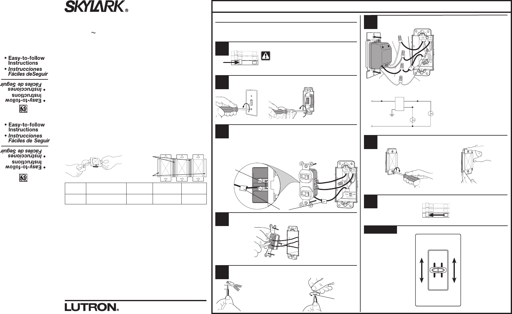
Wire the control:
•Connectthegreengroundwireonthe
dimmer to the green or bare copper
ground wire in the wallbox. If there
is no ground wire in your wallbox,
consult an electrician.
(See important note 3.)
•Connecttheblackwireonthedimmer
to the tagged wallbox wire removed
from the switch (feed wire from
breaker panel).
•Connecttheredwireonthedimmerto
the wallbox wire leading to one of the
lights.
•Connecttheyellowwireonthe
dimmer to the wallbox wire leading to
the other light.
Mount and align dimmer. Install wallplate.
Turn power ON.
Operation
Installation
For installations involving more than one control in a wallbox, refer to Multi-Unit
Installations before beginning.
Separate wires are required in the wallbox for each light circuit.
Turn power OFF at circuit breaker or remove fuse.
For new construction go to Step 5.
Remove wallplate. Pull switch from wall.
Verify application. This dimmer mounts in a single-gang
wallbox and controls two independent lights, 300 W
maximum for each slider. Independent wire must be
provided for each light.
Disconnect switch wires.
Prepare wires. Twist and trim wires to the proper length
indicated below when completing Step 6.
3/8 in
(10 mm)
Strip length: 3/8 in (10 mm) for 14–18 AWG
(1.5–0.75 mm
2
).
Note: Wire connectors provided are suitable
for copper wire only. For aluminum wire,
consult an electrician.
Use to join the following combinations:
One 14 AWG (1.5 mm
2
) wire with one
16 or 18 AWG (1.5 or 0.75 mm
2
) wire.
Green
Bright
Dim
Off
LIGHT
Bright
Dim
Off
LIGHT
Turn screws to loosen.
Break-
off fin
Tag
Tag
Tag the wire that is connected to the feed side
of the switch (the side with the break-off fin).
Twist wire
connector tight.
Be sure no
bare wire is
exposed.
ON
OFF
ON
OFF
ON
OFF
Align control and
tighten screws.
Start screws.
Live
Black
Ground
Red
Yellow
Light
Light
Neutral
Green
ON
OFF
ON
OFF
ON
OFF
Lutron Technical Support Center 1.800.523.9466 24 hrs / 7 days www.lutron.com
1
2
3
4
5
6
7
8
120 V
60 Hz
~
120 V~
60 Hz
WARNING: Shock Hazard. May result in
serious injury or death. Turn off power at
circuit breaker before installing the unit.