
Installation Guide

®
SPECIFICATION SUBMITTAL Page
Job Name:
Job Number:
Model Numbers:
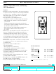
Lutron® GFCI – Tamper Resistant, Self-Testing Receptacles
369964a 4 08.13.15
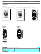
A: One cable entering the box OR B: Two cables entering the box
LINE cable brings
power to the GFCI
Grounding connection
to box (if box has a
grounding terminal)
Wire
connector
LINE cable brings
power to the GFCI
Wire
connector
Grounding connection
to box (if box has a
grounding terminal)
Electrical
box
LOAD
cable feeds
power to other
receptacle(s)
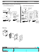
About wire connections
Clockwise, 2/3 of the way
around the screw
Wire
1 in
Wire
5/8 in
Insert wire to the
bottom of hole and
tighten down screw
Side Wire
Back Wire
About wire connections
Clockwise, 2/3 of the way
around the screw
Wire
Wire
Insert wire to the
bottom of hole and
tighten down screw
Side Wire
Back Wire
Electrical box
Yellow sticker
remains in
place to cover
the LOAD
terminals
(16 mm)
(25.4 mm)
1 in
(25.4 mm)
5/8 in
(16 mm)
Wiring Diagrams (choose one or the other)
Mounting
TEST
TEST
RESET
RESET
4