
Installation Guide

Wiring the Dimmer
Lutron Electronics Co., Inc.
7200 Suter Road
Coopersburg, PA 18036-1299, U.S.A.
Made and printed in U.S.A. 1/10 P/N 030-1274 Rev. A
Limited Warranty (Valid only in U.S.A., Canada, Puerto Rico and the Caribbean.)
Lutron will, at its option, repair or replace any unit that is defective in materials or manufacture within one year after purchase. For warranty service, return
unit to place of purchase or mail to Lutron at 7200 Suter Rd., Coopersburg, PA 18036-1299, postage pre-paid.
THIS WARRANTY IS IN LIEU OF ALL OTHER EXPRESS WARRANTIES, AND THE IMPLIED WARRANTY OF MERCHANTABILITY IS LIMITED TO ONE
YEAR FROM PURCHASE. THIS WARRANTY DOES NOT COVER THE COST OF INSTALLATION, REMOVAL OR REINSTALLATION, OR DAMAGE RESULT-
ING FROM MISUSE, ABUSE, OR DAMAGE FROM IMPROPER WIRING OR INSTALLATION. THIS WARRANTY DOES NOT COVER INCIDENTAL OR CON-
SEQUENTIAL DAMAGES. LUTRON’S LIABILITY ON ANY CLAIM FOR DAMAGES ARISING OUT OF OR IN CONNECTION WITH THE MANUFACTURE,SALE,
INSTALLATION, DELIVERY, OR USE OF THE UNIT SHALL NEVER EXCEED THE PURCHASE PRICE OF THE UNIT.
This warranty gives you specific legal rights, and you may have other rights which vary from state to state. Some states do not allow the exclusion or lim-
itation of incidental or consequential damages, or limitation on how long an implied warranty may last, so the above limitations may not apply to you.
This product may be covered under one or more of the following U.S. patents: 5,207,317; 5,637,930; 6,005,308; D558,151; D566,659; and corre-
sponding foreign patents. U.S. and foreign patents pending. Lutron, Claro, Diva, and Skylark are registered trademarks and Satin Colors is a trademark
of Lutron Electronics Co., Inc. NEC is a registered trademark of National Fire Protection Association, Quincy, Massachusetts.
© 2010 Lutron Electronics Co., Inc.
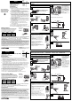
Installation
For installations involving more than one Dimmer in a wallbox, refer to
Multigang Installations before beginning.
ON
OFF
ON
OFF
ON
OFF
Turn screws
to loosen.
Disconnect Switch Wires
Backwired:
Insert screwdriver. Pull wire out.
Screw Terminals:
Turn screws to loosen.
ON
OFF
ON
OFF
ON
OFF
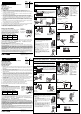
Turn Power ON
Mount and Align Dimmer and Install Wallplate
Lutron Electronics Co., Inc.
7200 Suter Road
Coopersburg, PA 18036-1299, U.S.A.
Hecho e impreso en E.U.A. 1/10 P/N 030-1274 Rev. A
Unipolar Atenuadores Electrónicos de Bajo Voltaje
Clasificado para 120 V~ 60 Hz
Adquiera la placa de pared por separado.
Notas Importantes
Favor de leer antes de instalar.
1. Precaución: Para evitar un recalientamiento o el posible daño a otros equipos, no instale para controlar receptác
los,accesorios fluorescentes, equipos motorizados, o equipos subministrados por transformadores.
2. Use solamente para controlar el lado primario de luces de bajo voltaje subministrados por transformadores
electrónicos, o en combinación de luces incandescentes.
3. Este producto necesita un alambre neutro en la caja de embutir. Si no existe un alambre neutro, llame a un
electricista calificado para la instalación.
4.
Si en la caja de embutir no hay acceso a una conexión de tierra, la norma NEC
®
2008, Artículo 404.9 permite
instalar como reemplazo un atenuador sin conexión a tierra, en tanto se utilice una placa de pared de plástico
no combustible. Para este tipo de instalación, aísle o elimine el conductor verde de tierra del atenuador y
utilice una placa de pared adecuada tal como la Claro
TM
o Satin Colors
TM
de Lutron
®
.
5. Algunos fabricantes no recomiendan la atenuación de transformadores de estado sólido. Para determinar si un
accesorio puede ser atenuado, consulte Lutrón o el fabricante del accesorio.
6. Este
atenuador
está protejido contra sobre cargas. Si se excede el vatiaje clasificado, la corriente al circuito se
apagará hasta que el
atenuador
se enfrié. Si esto ocurre, remueva la carga excesa del circuito.
7. Durante la operación normal, el atenuador puede estar tibio at tacto.
8. En aplicaciones de fases multiples, use un neutral en cada fase conteniendo un circuito atenuado.
9. Para instalaciones nuevas, instale un interruptor de ensayo antes de instalar el atenuador.
10. Instale de acuerdo con los códigos nacionales y locales gobernando la electricidad.
11. Limpie la unidad con un
paño suave y húmedo únicamente
. No use agentes químicos de limpieza.
Asistencia Técnica
Si tiene preguntas referente a la instalación o operación de este producto, llame al
Centro de Soporte Técnico
de Lutron
. Por favor suministre el numero exacto del modelo con su llamada.
1.800.523.9466 (E.U.A., Canadá, y el Caribe), +1.888.235.2910 (México) +1.610.282.3800 (otros países)
Fax +1-610-282-6311 Internet: www.lutron.com
Garantía Limitada
(Válido solamente en los E.U.A., Canadá, Puerto Rico, y el Caribe.)
Lutron reparará o reemplazará, a su criterio, cualquier unidad cuyos materiales o fabricación resulten defectuosos en el término de un año después de
la fecha de compra. Para obtener servicio de garantía, la unidad debe devolverse al lugar de compra o enviar, con franqueo pago, a Lutron, 7200 Suter
Road, Coopersburg, Pennsylvania 18036-1299.
ESTA GARANTÍA SE OFRECE EN LUGAR DE CUALQUIER OTRA GARANTÍA EXPRESA. LA GARANTÍA IMPLÍCITA DE COMERCIABILIDAD ESTÁ LIMI-
TADA A UN AÑO, A PARTIR DE LA FECHA DE COMPRA. ESTA GARANTÍA NO CUBRE LOS COSTOS DE INSTALACIÓN, DESMONTAJE NI
REINSTALACIÓN. TAMPOCO CUBRE DAÑOS RESULTANTES DE UN USO IMPROPIO O ABUSO, NI DAÑOS DEBIDOS A UNA INSTALACIÓN O
CONEXIÓN INCORRECTA. ESTA GARANTÍA NO CUBRE DAÑOS INCIDENTALES NI RESULTANTES. LA OBLIGACIÓN DE LUTRON CON RESPECTO A
CUALQUIER RECLAMACIÓN POR DAÑOS RELACIONADOS CON LA FABRICACIÓN, VENTA, INSTALACIÓN, ENTREGA, USO, REPARACIÓN O REEM-
PLAZO DE LA UNIDAD, NO SUPERARÁ, EN NINGÚN CASO, EL PRECIO DE COMPRA.
Esta garantía otorga derechos legales específicos, pero se podría tener otros derechos, que varían de un estado a otro. Algunos estados no permiten la
exclusión o limitación de daños incidentales ni resultantes, ni limitaciones en la duración de una garantía implícita, por lo cual es posible que las limita-
ciones mencionadas anteriormente no correspondan en ciertos casos.
Este producto puede estar cubierto debajo de una o más de unas de las siguientes patentes de E.U.A.: 5,207,317; 5,637,930; 6,005,308; D558,151;
D566,659; y las patentes extranjeras correspondientes. Patentes de E.U.A. y extranjeros están pendiente. Lutron es una marca registrada y Claro y
Satin Colors son marcas de Lutron Electronics Co., Inc. NEC es una marca registrada de National Fire Protection Association, Quincy, Massachusetts.
© 2010 Lutron Electronics Co., Inc.
Elimine todas las
secciones laterales
internas (sombreadas).
No elimine las secciones
laterales éxternas.
Single Pole Electronic
Low-Voltage Dimmers
Rated at 120 V~ 60 Hz
Purchase wallplate separately.
Important Notes
Please read before installing.
1. Caution: To avoid overheating and possible damage to other equipment, do
not use to control receptacles, fluorescent lighting fixtures, motor-operated
or transformer-supplied appliances.
2. Use only to control the primary side of electronic transformer-supplied
low-voltage lighting, or in combination with incandescent lamps.
3. This product requires a neutral wire in the wallbox. If a neutral wire is not
present, contact a licensed electrician for installation.
4. When no "grounding means" exist within the wallbox then the NEC
®
2008,
Article 404.9 allows a dimmer without a grounding connection to be
installed as a replacement, as long as a plastic, noncombustible wallplate
is used. For this type of installation, cap or remove the green ground wire
on the dimmer and use an appropriate wallplate such as Claro
®
or Satin
Colors
TM
series wallplates by Lutron
®
.
5. Some fixture manufacturers do not recommend dimming their solid-state
transformers. To determine if a fixture may be dimmed, consult Lutron or
the fixture manufacturer.
6. This Dimmer is overload protected. If the rated wattage is exceeded, power
to the circuit will shut off until the Dimmer cools. If this occurs, remove
excess load from the circuit.
7. Dimmer may feel warm to the touch during normal operation.
8. In multi-phase applications, use a separate neutral for each phase
containing a dimmed circuit.
9. For new installations, wire a test switch before installing the Dimmer.
10. Install in accordance with all national and local electrical codes.
11. Clean Dimmer with a
soft damp cloth only
. Do not use any chemical cleaners.
Technical Assistance
If you have questions concerning the installation or operation of this product, call the
Lutron Technical Support Center
.
Please provide exact model number when calling. 1.800.523.9466 (U.S.A., Canada, and the Caribbean)
+1.888.235.2910 (México) +1.610.282.3800 (Other countries) Fax +1.610.282.6311 Internet: www.lutron.com
Remove all inner side
sections (shaded).
Do not remove outer
side sections.
Important Wiring Information
Twist wire
connector tight.
Be sure no bare wire
is exposed.
When making wire connections, follow the recommended strip lengths and combinations
for the supplied wire connectors. Note: Wire connectors provided are suitable for
copper wire only.
For aluminum wire, consult an electrician.
Turn Power OFF at Circuit Breaker or Remove Fuse
Start screws.
Align Dimmer and tighten screws.
• Easy-to-follow Instructions
• Instrucciones Fáciles de Seguir
• Instruções Fáceis de Seguir
• Instructions Faciles à Suivre
030-1274
Español
English
Note: Wire location on Dimmer may vary depending on model.
Green
Ground
White
Neutral
Load
Ground
White
Yellow
Green
Black
Live
YellowBlack
• Connect the green Dimmer
ground wire to the bare copper
or green ground wire in the
wallbox (see Important Note 4).
• Connect the black wire on the
Dimmer to the wire leading to
the circuit breaker or fuse box.
• Connect the yellow wire on the
Dimmerto the wire leading to
the load.
• Connect the white wire on the
Dimmer to neutral.
Remove Switch Mounting Screws and Pull Switch
from Wall
Dele vueltas al
tornillo para
soltarlo.
Instalación
Para instalaciones múltiples en una caja de embutir, antes de empezar vea las
instrucciones de unidades múltiples.
ON
OFF
ON
OFF
ON
OFF
Retire la placa de la pared. Saque el interruptor de la pared.
Apague la corriente en la caja de circuitos o remueva los
fusibles.
Terminales de Tornillos:
Dele vueltas al tornillo para soltarlo.
Desconecte los alambres del interruptor.
Conexiones Posteriores:
Coloque el destornillador.
Saque el alambre.
Conecte el atenuador
Nota: la ubicación del cable en el atenuador puede
variar, dependiendo del modelo.
• Conecte el alambre de tierra
verde del atenuador al alam-
bre de cobre desnudo o de
tierra verde en la caja de
embutir (vea Notas
Importantes 4).
• Conecte el alambre negro del
atenuador al alambre que va a
la caja de circuitos o caja de
fusibles.
• Conecte el alambre amarillo
del atenuador al alambre que
va a la carga.
• Conecte el alambre blanco
del atenuador al neutral.
Instrucciones importantes de cableado
Tuerza el conectador
de alambre hasta
que este firme.
Asegúrese que no
queden alambres
expuestos.
Cuando se conecten cables, la longitud expuesta de los extremos y la combinación de
conexiones deberán estar de acuerdo con las recomendaciones para el conector
suministrado. Nota: Los conectores suministrados son apropiados para
alambres de
cobre únicamente.
Consulte a un electricista en caso de usar conductores de aluminio.
Pequeño
Grande
ON
OFF
ON
OFF
ON
OFF
Encienda la corriente.
Monte y alinie el atenuador. Instale la placa de pared.
Coloque los tornillos.
Alinie el atenuador y apriete
los tornillos.
Blanco
Tierra
Blanco
Tierra
Neutral
Verde
Amarillo
Verde
Negro
Amarillo
Negro
Vivo
Instalación de Unidades Múltiples
Cuando combine controles en la caja de embutir, elimine todas las
secciones laterales internas antes de conectar los alambres. Para
eliminar las secciones laterales internas, use un alicate para doblarlas
cuidadosamente hasta que se separen. Repita este proceso para cada
sección que necesite eliminar. Reducción de la capacidad del control
se requiere en este caso. Use la tabla siguiente para determinar la
capacidad nueva del control.
Multigang Installations
When combining controls in a wallbox, remove all inner side
sections prior to wiring. Use pliers to bend side section up and
down until it breaks off. Repeat for each side section to be
removed. Reduction of control capacity is also required.
Refer to chart below for maximum control capacity.
Sin Eliminar Una Sección Dos Secciones
Secciones Eliminada Eliminadas
300 W máx. 250 W máx. 200 W máx.
600 W máx. 500 W máx. 400 W máx.
120 V~
60 Hz
600 W
DLELV-600PL
LGELV-600P
LXELV-600PL
300 W
DVELV-300P
DVSCELV-300P
SELV-300P
SELVB-300P
SELVC-300P
LGELV-300P
LGELVB-300P
Models:
Carga
120 V~
60 Hz
No Sides 1 Side 2 Sides
Removed Removed Removed
300 W max. 250 W max. 200 W max.
600 W max. 500 W max. 400 W max.
Lutron Technical Support Center 1.800.523.9466 24 hrs / 7 days www.lutron.com
Centro de Soporte Técnico de Lutron +1.888.235.2910 24 horas / 7 días www.lutron.com
11
22
33
44
55
66
11
22
33
44
55
66
Small
Large
Warning: Shock hazard. May result in serious
injury or death. Turn off power at circuit
breaker before installing the unit.
Small:
Strip insulation 3/8 in (10 mm) for 14 AWG (1.5 mm
2
) wire.
Strip insulation 1/2 in (13 mm) for 16 AWG (1.0 mm
2
) or
18 AWG (0.75 mm
2
) wire.
Use to join one 14 AWG (1.5 mm
2
) supply wire with one
16 AWG (1.0 mm
2
) or 18 AWG (0.75 mm
2
) control wire.
Large:
Strip insulation 1/2 in (13 mm) for 10 AWG (6 mm
2
),
12 AWG (2.5 mm
2
), or 14 AWG (1.5 mm
2
) wire.
Strip insulation 5/8 in (16 mm) for 16 AWG (1.0 mm
2
) or
18 AWG (0.75 mm
2
) wire.
Use to join one or two 12 AWG (2.5 mm
2
) or
14 AWG (1.5 mm
2
) supply wires with one 10 AWG (6 mm
2
),
12 AWG (2.5 mm
2
), 14 AWG (1.5 mm
2
), 16 AWG (1.0 mm
2
), or
18 AWG (0.75 mm
2
) control wire.
600 W
DLELV-600PL
LGELV-600P
LXELV-600PL
300 W
DVELV-300P
DVSCELV-300P
SELV-300P
SELVB-300P
SELVC-300P
LGELV-300P
LGELVB-300P
Modelos:
Pequeño:
Quite el aislamiento 10 mm (3/8 in) para conductores calibre 1,5 mm
2
(14 AWG).
Quite el aislamiento 13 mm (1/2 in) para conductores calibre
1,0 mm
2
(
16
AWG)
ó
0,75 mm
2
(
18 AWG
)
.
Úsese para conectar un conductor de suministro calibre
1,5 mm
2
(14 AWG) con un conductor de control calibre 1,0 mm
2
(16 AWG) ó
0,75 mm
2
(18 AWG).
Grande:
Quite el aislamiento 13 mm (1/2 in) para conductores calibre 6,0 mm
2
(10 AWG), 2,5 mm
2
(12 AWG) ó 1,5 mm
2
(14 AWG).
Quite el aislamiento 16 mm (5/8 in) para conductores calibre
1,0 mm
2
(16 AWG) ó 0,75 mm
2
(18 AWG).
Úsese para conectar uno o dos conductores de suministro calibre 2,5 mm
2
(12 AWG) ó 1,5 mm
2
(14 AWG) con uno de control calibre 6,0 mm
2
(10 AWG),
2,5 mm
2
(12 AWG), 1,5 mm
2
(14 AWG), 1,0 mm
2
(16 AWG) ó 0,75 mm
2
(18 AWG).
Precaución: Peligro de descargas eléctricas.
Puede causar lesiones graves o letales. Corte el
suministro eléctrico en el magnetotérmico
antes de instalar la unidad.