TX1500U SMART TEMP ® UNIVERSAL 5/1/1-DAY PROGRAMMABLE THERMOSTAT (FOR BOTH CONVENTIONAL AND HEAT PUMP SYSTEMS) I N S TA L L AT I O N A N D O P E R AT I N G I N S T R U C T I O N S 52104 IMPORTANT! • Please read all of these instructions carefully before beginning installation. • Label every wire terminal designation on your existing thermostat wiring before removing your old thermostat. • Ignore the color of the wires since they may not comply with any standard.
TX1500U Fan Mode Switch LCD Display Screen FAN AUTO TU DAY ON 72 FAN 5:36 P HEAT F̊ TEMPERATURE HEAT OFF FILTER %LEFT SETBACK 40 74 F̊ SET SET Set Slide Switch RUN DAY/TIME TEMP PROG AIR FILTER HOLD EMER COOL NEXT LUX TX1500U System Mode Switch UP / DOWN Buttons SYSTEM COMPATIBILITY: The electrical rating for this thermostat is 1.5 Amps per terminal, with a maximum total combined load of 3.0A for all terminals combined.
FEATURES: • • • • • • • • • • • • • • • • • • • • • • • 1 or 2-Heat / 1-Cool, 5/1/1-day programming Universal Compatibility for all system types Weekdays, Saturday, and Sunday can be programmed separately Exclusive LUX ® Speed Slide TM for easy programming User-selectable periods per day (2 or 4) User-selectable programmable or non-programmable operation LuxLight ® EL (Electro-Luminescent) lighted display Programmable air filter life timer Graphical filter monitor Keypad lockout for unauthorized users Manu
MOUNTING LOCATION: On replacement installations, mount the new thermostat in place of the old one unless the conditions listed below suggest otherwise. On new installations, please follow these general guidelines: 1. Mount the thermostat on an inside wall, about 5 ft. (1.5m) above the floor. 2. Do not locate the thermostat where air circulation is poor such as in a corner, alcove, or behind a door that is normally left open. 3.
INSTALL THERMOSTAT BASE: Large Indentation: Front Housing Release Small Indentation: Door Release THERMOSTAT TOP VIEW 1. Strip wire insulation leaving only 3/8 in. (9.5mm) bare wire ends, and clean off any corrosion present. 2. Fill the wall opening with non-combustible insulation to prevent drafts from affecting the thermostat’s normal operation. 3. Route the wires through the opening in the new thermostat base plate, and hold the base against the wall.
WIRING DIAGRAM NOTES: (Important, please read all notes before connecting wires) • If the information provided in the following wiring diagrams does not clearly represent or match your system, please refer to the “TECHNICAL ASSISTANCE” section of this manual, and contact us before removing any of your existing thermostat wiring. • All of the dashed wires shown in the wiring diagrams are either optional, or their usage depends upon your specific system type or brand.
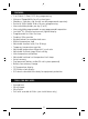
WIRING DIAGRAMS: DIAGRAM SYSTEM TYPE / DESCRIPTION #1 CONVENTIONAL: HEATING .............................................8 1-STAGE OR 2-STAGE 2, 3, 4, 5 WIRES #2 CONVENTIONAL: HEATING .............................................9 3-WIRE ZONE VALVE 3, 4 WIRES #3 CONVENTIONAL: COOLING............................................10 1-STAGE 3, 4 WIRES #4 CONVENTIONAL: HEATING AND COOLING ...........................11 1-STAGE HEAT 4, 5 WIRES #5 CONVENTIONAL: HEATING AND COOLING .................
FAN WIRE MAY NOT BE PRESENT IN ALL SYSTEMS B G RH SYSTEM 24V TRANSFORMER HEATER STAGE 1 O P T I O N A L B* 4 V C X C W1 W2 W2 RH STAGE 2 A F W W1 R SYSTEM COMMON RC G Y Factory RH-RC Jumper Wire Installed 1-STAGE OR 2-STAGE, HEATING ONLY (INCLUDING MILLIVOLT) (2-WIRE HEAT USE “RH” & “W1”) NOTE: THE BLACK TERMINAL LETTERS ARE TYPICAL, GRAY TERMINAL LETTERS ARE BRAND SPECIFIC FAN O 2, 3, 4, 5 WIRES #1
B G CLOSE 3-WIRE ZONE VALVE OPEN OPEN = Heat On CLOSE = Heat Off B* 4 V C X C W1 A W2 RH A W W1 R RH SYSTEM COMMON RC SYSTEM 24V TRANSFORMER Y Factory RH-RC Jumper Wire Installed HOT WATER HEATING ONLY (WITH A 3-WIRE ZONE VALVE) NOTE: THE BLACK TERMINAL LETTERS ARE TYPICAL, GRAY TERMINAL LETTERS ARE BRAND SPECIFIC O 3, 4 WIRES O P T I O N A L #2
B Y1 F 6 Y Y G FAN G W1 SYSTEM COMMON RH SYSTEM 24V TRANSFORMER V RC R RC Factory RH-RC Jumper Wire Installed 1-STAGE, COOLING ONLY A AIR CONDITIONER W2 C O P T I O N A L B* X C NOTE: THE BLACK TERMINAL LETTERS ARE TYPICAL, GRAY TERMINAL LETTERS ARE BRAND SPECIFIC O 3, 4 WIRES #3
FAN G RC 6 SYSTEM 24V TRANSFORMER C O P T I O N A L B* C 4 W2 X HEATER A W1 W W1 SYSTEM COMMON V RH R Y1 RH F RC Y Y G AIR CONDITIONER B Factory RH-RC Jumper Wire Installed CONVENTIONAL (NON HEAT PUMP) 1-STAGE HEATING AND 1-STAGE COOLING NOTE: THE BLACK TERMINAL LETTERS ARE TYPICAL, GRAY TERMINAL LETTERS ARE BRAND SPECIFIC O 4, 5 WIRES #4
FAN G RC 6 SYSTEM 24V TRANSFORMER HEATER STAGE 2 C O P T I O N A L B* C 4 W2 W2 X STAGE 1 A W1 W W1 SYSTEM COMMON V RH R Y1 RH F RC Y Y G AIR CONDITIONER B Factory RH-RC Jumper Wire Installed CONVENTIONAL (NON HEAT PUMP) 2-STAGE HEATING AND 1-STAGE COOLING NOTE: THE BLACK TERMINAL LETTERS ARE TYPICAL, GRAY TERMINAL LETTERS ARE BRAND SPECIFIC O 5, 6 WIRES #5
G V 6 V R RH RH COOL 24V TRANSFORMER C B* C 4 HEATER W2 X A W1 W W1 HEAT 24V TRANSFORMER SYSTEM COMMON R Y1 F RC RC Y Y G AIR CONDITIONER B Factory RH-RC Jumper Wire REMOVED 1-STAGE HEATING AND 1-STAGE COOLING WITH TWO SEPARATE 24V TRANSFORMERS NOTE: THE BLACK TERMINAL LETTERS ARE TYPICAL, GRAY TERMINAL LETTERS ARE BRAND SPECIFIC FAN O 5, 6 WIRES O P T I O N A L #6
O B Y1 F 6 Y Y G FAN G W1 A HEAT PUMP W2 C CUSTOMER INSTALLED Y-W1 Jumper Wire SYSTEM COMMON RH SYSTEM 24V TRANSFORMER V RC R RC Factory RH-RC Jumper Wire Installed SINGLE-STAGE HEAT PUMP SYSTEM WITH NO AUX OR EMERGENCY HEAT O P T I O N A L B* X C NOTE: THE BLACK TERMINAL LETTERS ARE TYPICAL, GRAY TERMINAL LETTERS ARE BRAND SPECIFIC REVERSING VALVE O ** Use “O” or “B” Terminals, Never Both 4, 5 WIRES #7
O B FAN G Y1 F RH HEAT PUMP W1 A AUX / EMERG.
HARDWARE SETUP OPTIONS: On the thermostat’s circuit board, there is a row of DIP switches, labeled #1 through #8. The position of these switches will change how the thermostat operates, and also how information is conveyed to you on the LCD display screen. If you make any changes to these options, the changes are not recognized unless you either: change the position of the HEAT/OFF/COOL mode switch, or press the “HW RST” (Hardware Reset) button on the circuit board.
SWITCH #3 (PERIODS): [OFF/DOWN = 4, default] The thermostat uses four temperature program periods in both heating and cooling (MORN, DAY, EVE, and NITE). Each period has a separate start time and a set temperature. [ON/UP = 2] The thermostat operates in the same manner as above, however there are only two temperature program periods for heating and cooling (DAY and NITE).
SWITCH #8 (BATTERY MONITOR): [OFF/DOWN = ON, default] This setting, regularly monitors the battery level, and shows “LOW BAT” on the screen if the batteries need to be replaced. Use this setting at all times when batteries are present in the thermostat. [ON/UP = OFF] This setting only applies if you are NOT physically using batteries in the thermostat, and are powering the thermostat entirely from the system (“C” wire terminal).
AUTO / ON, FAN MODE SWITCH: When this switch is in AUTO, the blower fan (if present in your system) will automatically cycle on and off by itself while heating or cooling is running. When in the ON position, the blower fan will run constantly with or without a demand for heating or cooling, even when the System Mode switch is in the OFF position. NOTE: The Fan Mode switch only works if your system provides a wire for the thermostat’s “G” wire terminal, to control a blower fan.
NEXT BUTTON: This button is mostly used while setting items such as software options, and temperature program periods. When there are several items on the screen that can be changed, usually one of them is flashing indicating that it can be adjusted. Pressing the NEXT button will cycle through which item is flashing. OPERATING INSTRUCTIONS: SET DAY AND TIME: Place the Set Slide Switch into the DAY/TIME position. With the day flashing, press UP or DOWN to set the day of the week.
primary heating source. This will not only prevent the heat pump from wasting energy if outdoor temperatures are too low to support efficient operation, but it could also prevent damage to the heat pump if outside temperatures are below the manufacturer’s recommendations. As every heat pump has different operating characteristics, you should refer to your heat pump literature to determine when to disable the heat pump and run in Emergency Heat mode.
STATIC NOTICE: This thermostat is protected against normal static electric discharges, however to minimize the risk of damaging the unit in extremely dry weather, please touch a grounded metal object before touching your thermostat. TEMPERATURE PROGRAMS: By default, this thermostat has 4 separate program periods for both Heat and Cool mode, they are: MORN, DAY, EVE, and NITE. Each period ends at the start time of the following period.
ADVANCED FEATURES: TEMPERATURE SWING AND OFFSET SETTING: A thermostat works by turning your heating or cooling system on and off whenever the room temperature varies from the desired set-point temperature. The amount of this variation is called the swing. Generally your system should cycle on about 3 to 6 times per hour. A smaller swing number makes the system cycle more frequently, so the room temperature is more precise and constant.
71 70 69 68 Cut-In / Cut-Out (1st Stage) 70˚F Set Temperature Swing Setting= #2 (+/- 0.
TEMPERATURE CALIBRATION: The internal temperature sensor in this thermostat is accurately calibrated at the factory, and in most cases alterations to this setting should not be needed. The Temperature Calibration feature allows you to manually offset the measured temperature by as much as plus or minus 5°F (3°C) degrees from its original value. This feature can be useful to match or synchronize this thermostat to another one or more, if multiple thermostats are used in the same home.
the screen, you can either wait for the screen to advance forward on its own, or press the NEXT button (behind the door) one time to jump ahead rapidly. Now use the UP/DOWN buttons to select your desired set temperature that will be used for the Setback duration. Just like the previous step, you can either wait for the screen to advance on its own, or press the NEXT button to advance and return to the Normal Run screen.
TO SET THE COOL LIMIT STOP: Place the System Mode switch in the OFF position, and the Set Slide switch in the RUN position. Press and hold the DOWN button while sliding the System Mode switch from OFF to COOL. The words “TEMP STOP” and “LOCK CODE” will appear on the screen, along with two digits. Use the UP/DOWN buttons to select the proper code to access the cool limit setting. Press the NEXT button to accept the setting.
TO LOCK THE KEYPAD: Start with the System Mode switch in either the HEAT or COOL positions, and the Set Slide switch in the RUN position. Perform a single press of each button, in the following sequence: NEXT, NEXT, NEXT, HOLD. TO UNLOCK THE KEYPAD: Start with the System Mode switch in either the HEAT or COOL positions, and the Set Slide switch in the RUN position. Perform a single press of each button, in the following sequence: NEXT, NEXT, NEXT, HOLD.
UP and DOWN buttons together at the same time, and the usage counter will return to the beginning of the value that it originally started counting from. Refer to the previous paragraph, should you wish to change the starting value for the filter monitor. Return the Set Slide switch to the RUN position when you are finished.
Reset button (the LCD display screen will become fully populated). Continue to hold the NEXT and HOLD buttons until the LCD display screen returns to normal. All compressor protection delays (in all modes of operation) will be disabled for 5 minutes. After the 5-minute duration has expired, the thermostat will return to normal operation automatically. BATTERY REPLACEMENT: This thermostat is powered by two “AA” Alkaline batteries.
LIMITED WARRANTY: If this unit fails because of defects in materials or workmanship within three years of the date of original purchase, LUX will, at its option, repair or replace it. This warranty does not cover damage by accident, misuse, or failure to follow installation instructions. Implied warranties are limited in duration to three years from the date of original purchase. Some states do not allow limitations on how long an implied warranty lasts, so the above limitation may not apply to you.
TU DAY 72 FAN 5:36 P HEAT F̊ FILTER %LEFT SETBACK 40 74 F̊ SET HOLD Mt. Laurel, New Jersey 08054, USA http://www.luxproducts.