Table of Contents Table of Contents . . . . . . . . . . . . . . . . . . . . . . . . . . . . . . . . . . . . . . . . . Parts List & Hardware. . . . . . . . . . . . . . . . . . . . . . . . . . . . . . . . . . . . . . Assembly and Installation Assembly of the right and left frame . . . . . . . . . . . . . . . . . . . . . . . . . . . . . Place the crank adjustment housing . . . . . . . . . . . .
AA x1 AC x4 AB x1 BA x2 DA x1 DB x1 DC x1 FB*x5 M6x48 JB*x5 M6x73 FA x2 HA x1 CA x1 JA x1 BB x2 GA x1 MA x4 EA x1 M5 CB*x17 M4 Includes locking bolt M4 M8x15 HB x1 HC x1 KB*x3 M6x36 - Includes an *extra spare part 3 / 12
1 Assembly of the right and left frame Tighten casters fully with included wrench BB EA BA BB BA AC AC AC AC AB Mallet AA Gather Parts: AA, AB, AC, BA, BB, EA 4 / 12
2 Place the crank adjustment housing CA Assistance Recommended Gather Parts: CA 5 / 12
3 Attach the crank adjustment housing CBx4 CA CBx4 CA CBx4 DA CA CBx4 Gather Parts: DA 6 / 12 + CB x16 M8x15
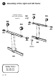
4 Assembly of the cross bars Assistance Recommended AB FB AA FB FA FB FA FB FA DB Make sure the indented center hole of the cross bars FA are facing towards the casters Gather Parts: FA, DB + FB x4 M6x48 7 / 12
5 Flip desk upright and attach crank handle 1 Assistance Recommended Handle should have only 13/4” of clearance when attached correctly. GA 2 GAx1 Gather Parts: GA 8 / 12 IMPORTANT: Install the OPTIONAL electric (SOLD SEPARATELY) before attaching the desk top to the frame.
6 Fasten the rotating hex rod 1 2 HA HB HC HA HA 3 HA HB HA HC DC HB 4 Gather Parts: DC + With allen wrench DC fasten the locking bolt HB clock-wise until the nut locks in place.
7 Attach the desk surface Assistance Recommended JA JB Gather Parts: JA 10 / 12 JB DB + JB JB x4 M6x73 JB
8 Finish assembly and tighten bolts MA x4 KB KB Gather Parts: MA + DB KB x2 M6x36 11 / 12
06/07/2016