USER Guide Pro-WAV™ Wi-Fi Range Extender SYSTEM For use with the D-Link DWL-2100AP Model Number: PW-FC1 - Single Antenna PW-FC1 - Dual Antenna
Pro-WAV Wi-Fi Range Extender System Model Number: PW-FC1 INSTALLATION GUIDE © 2009 by Luxul Wireless, Inc. All rights reserved. No part of this publication may be modified or adapted in any way, for any purposes without permission in writing from Luxul Wireless, Inc. (Luxul). The material in this manual is subject to change without notice. Luxul reserves the right to make changes to any product to improve reliability, function, or design.
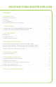
SHOCK-WAV SIGNAL BOOSTER USER GUIDE Contents 1 - INTRODUCTION . . . . . . . . . . . . . . . . . . . . . . . . . . . . . . . . . . . . . . . . . . . . . . . . . . . . . . . . . . . . 2 1.1 Document Conventions . . . . . . . . . . . . . . . . . . . . . . . . . . . . . . . . . . . . . . . . . . . . . . . . . . . . . . . . . . . . . . . . 2 1.2 Warnings . . . . . . . . . . . . . . . . . . . . . . . . . . . . . . . . . . . . . . . . . . . . . . . . . . . . . . . . . . . . . . . . . . . . . . . . . . . . . 2 1.
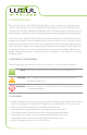
1 - INTRODUCTION The Luxul Wireless Pro-WAV Wi-Fi Range Extender System is designed to complement and enhance the performance of the D-Link DWL-2100AP Wireless Access Point (WAP). When combined with the DWL-2100AP and X-WAV XW-24-FP7 Flat Panel Antenna, it delivers up to the maximum approved transmit power, resulting in a farther reaching and higher performing network.
SHOCK-WAV SIGNAL BOOSTER USER GUIDE • Verify that the power connector and socket are accessible at all times during the operation of the equipment. • Do not work with power circuits in dimly lit spaces. • Do not install this equipment or work with its power circuits during thunderstorms or other weather conditions that could cause a power surge. • Verify there is adequate ventilation around the device, and that ambient temperatures meet equipment operation specifications.
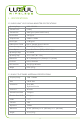
2 - SPECIFICATIONS 2.1 SHOCK-WAV™ WI-FI SIGNAL BOOSTER SPECIFICATIONS Operating Range 2400 - 2483 MHz Transmit Power (28dBm) Transmit Gain 20dB Typical (under D-AGC Control) Receive Gain 15dB Typical TX Input Power +8dBm to +24dBm Noise Figure 3.5dB Typical LED Indicators TX\RX Red for Transmit, Green for Receive Power Consumption 400mW (RX) 5W (TX) Max Power Options Power Over Ethernet (POE) or AC-DC adapter Operating Voltage 12 to 48VDC Operating Temp -4 F to +122F (-20c - +50c) Dime
SHOCK-WAV SIGNAL BOOSTER USER GUIDE 3 - GETTING STARTED 3.1 Precautions Before installing the Shock-WAV Wi-Fi Signal Booster and DWL-2100AP verify the following: • Do not install in wet or dusty areas without additional protection. Contact a Luxul Wireless representative for more information. • Verify the environment has a continuous temperature range between -4 F to +122F (-20c - +50c). 3.
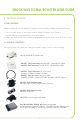
3.3 Additional Items Required Before installing your Shock-WAV Wi-Fi Signal Booster, be sure to have the following items available: • Ethernet cable for connection to your network source 3.4 Optional Products and Accessories Splitters and Surge Protectors: Signal splitters, lightning surge protectors, and other useful accessories are available for making the most of your Luxul Wireless purchase.
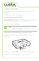
SHOCK-WAV SIGNAL BOOSTER USER GUIDE 4.1 Connecting the PW-FC1 - Single Antenna to the D-Link DWL-2100AP 1 2 Figure 2 5 4 Coax Cable 3 Using the supplied N-Male to RP-SMA-Male coax cable, connect the Shock-WAV Wi-Fi Signal Booster to your DWL-2100AP’s Antenna port . (Figure 2 ) 1. Be sure to connect the cable to the side of the Signal Booster labeled WAP 2. Next use the included N-Male to N-Male cable 3 connect the Shock-WAV Wi-Fi Signal Booster to the X-WAV XW-24-FP7 antenna 5.
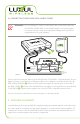
4.3 Connecting Power and Data Source cables WARNING!: Do not attempt to connect or disconnect any components while the D-Link DWL-2100AP WAP or Shock-WAV signal booster are plugged into power. Doing so may cause equipment damage and/or physical injury and will void your warranty. 1 2 3 Power Supply Coax Cable Ethernet Power Data Source Power Figure 4 Power connections are the same for both PW-FC1 units. The PW-FC1 - Single antenna is show in figure 4.
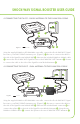
SHOCK-WAV SIGNAL BOOSTER USER GUIDE 5.1 Antenna Deployment Be sure you place the antenna so there is a minimum of 2 feet (.6 meters) of open space around it. Figure 5 Figure 6 Figure 5 (Single antenna) and 6 (Dual Antenna) show the recommended Antenna deployments and how loss of the signal coverage can happen due to bad antenna placement.
5.2 Antenna Direction For maximum coverage it is important to have your antenna pattern radiating in the correct direction. The pattern radiates out in a cone shape pattern away from the antenna. If the antenna is tipped at an angle, the pattern will radiate out at that angle. See Figure 7 for an example of pattern radiation. Figure 7 6 - REGULATORY COMPLIANCE This device is approved under the Luxul Wireless brand and designed to comply for use specifically with the D-Link DWL-2100AP.
SHOCK-WAV SIGNAL BOOSTER USER GUIDE 6.1 Health and Safety Recommendations Warnings for the use of Wireless Devices: Please observe all warning notices with regard to the usage of wireless devices Potentially Hazardous Atmospheres: You are reminded of the need to observe restrictions on the use of radio devices in fuel depots, chemical plants etc. and areas where the air contains chemicals or particles (such as grain, dust, or metal powders).
• The following safety precautions should be observed: −− Do not touch or move the antenna while the unit is transmitting or receiving. −− Do not hold any component containing the radio such that the antenna is very close or touching any exposed parts of the body, especially the face or eyes, while transmitting. −− Do not operate the radio or attempt to transmit data unless the antenna is connected; this behavior may cause damage to the radio.
SHOCK-WAV SIGNAL BOOSTER USER GUIDE 6.5 Industry Canada ( RSS-Gen Issue 2) In accordance with Industry Canada Regulations, this radio frequency power amplifier may only be used with a transmitter with which the amplifier has been certified by Industry Canada. The Industry Canada Identification Number for the transmitter with which this amplifier is permitted to operate is 4216A-WL2100AP This PW-FC1 - Single Antenna is designed to work with one XW-24-FP7 antenna.
Results may vary depending on building layout, type of construction and other environmental factors including Wi-Fi traffic, Microwaves Ovens, Cordless Phones, etc. FCC NOTICE: The use of all radio equipment is subject to regulations in each country. To comply with FCC part 15 rules in the United States, radio equipment must only be used in systems that have been FCC certified. It is the responsibility of the user/professional installer/operator to ensure that only approved equipment/systems are deployed.