
User's Manual


Lecip Arcontia confidential (V1.00 2019-05-13)
2. External/Electrical Interface and Access Card
Here is the detailed description of Pinout, connectors and function or available signals on
Access card.
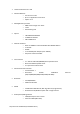
Fig 1. Access Card
L2R
Pos.
Conn.
Pin nr.
Interface
Function
Wire
Wire-end
ferrule
Digi-key
(mm
2
)
AWG
1
J2
1
RS232-1
RTS
0.25
24
966066-3
A136908-ND
2
2
CTS
0.25
24
3
3
GND
0.25
24
4
4
RXD
0.25
24
5
5
TXD
0.25
24
6
6
IGN
IGN
0.5
20
966067-1
A114629-ND
7
7
BATT FWD
0.5
20
8
J3
1
POWER
SUPPLY
BATT +
1.5
16
902-569-0000
9
2
BATT -
1.5
16
10
J4
1
ETHERNET
ETH RX-
1
0.25
24
11
2
ETH RX+
0.25
24
12
3
GND
0.25
24
13
4
ETH TX-
2
0.25
24
14
5
ETH TX+
0.25
24
15
6
RS232-2
GND
0.25
24
16
7
RTS
0.25
24
17
J5
1
CTS
0.25
24
18
2
RXD
0.25
24
19
3
TXD
0.25
24
20
4
RS485
485-B
0.25
24
21
5
GND
0.25
24
22
6
485-A
0.25
24
23
7
GPO1
OUT-A
0.5
20
24
J6
1
OUT-B
0.5
20
25
2
GPO2
OUT-A
0.5
20
26
3
OUT-B
0.5
20
27
4
GPI1
IN-A
0.5
20
28
5
IN-B
0.5
20
29
6
GPI2
IN-A
0.5
20
30
7
IN-B
0.5
20
1
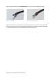
RX lines: Green, Green/White, with positions 6 and 3 in the RJ45 connector respectively
2
TX lines: Orange, Orange/White, with positions 2 and 1 in the RJ45 connector respectively