LX90xx GPS-Navigation System with variometer (Including LX9000 and LX9070) Version 4.0 LXNAV d.o.o. • Kidričeva 24a, 3000 Celje, Slovenia • tel +386 592 33 400 fax +386 599 33 522 info@lxnav.com • www.lxnav.
LX90xx system Version 4.0 1 2 3 4 5 6 February 2014 Important Notices 1.1 8 Limited Warranty 8 Basics 9 2.1 The LX9xx series at a glance 2.1.1 LX9000 Display Unit Features 2.1.2 LX9070 Display Unit Features 2.1.3 V9 Vario Unit Features 2.1.4 V80 Vario Unit Features 2.1.5 Interfaces 2.1.6 Internal Options 2.1.7 External Options 2.1.8 Simulator 2.1.9 Technical Data 2.1.9.1 LX9000 System 2.1.9.2 LX9070 System 2.1.10 Weight Packing Lists 3.1 3.2 3.
LX90xx system Version 4.0 February 2014 6.1.1 QNH and RES 6.1.1.1 QNH* 6.1.1.2 Safety Altitude 6.1.1.3 Altitude source 6.1.1.4 Magnetic Variation 6.1.1.5 ETA/ETE Calculation 6.1.1.6 Soaring Start* 6.1.2 Flight Recorder 6.1.3 Vario Parameters* 6.1.4 Display 6.1.5 Files and Transfers 6.1.5.1 Uploading User Airspace and Waypoints 6.1.5.2 Uploading Airspace and Airports Database 6.1.5.3 Managing Airspace 6.1.5.4 Managing Waypoints 6.1.5.5 Managing Airports 6.1.5.
LX90xx system Version 4.0 February 2014 6.1.12.10 AHRS 6.1.12.11 NMEA Output 6.1.12.12 Engine * 6.1.12.13 Flaps* 6.1.13 Polar and Glider* 6.1.14 Profiles and Pilots 6.1.15 Language 6.1.16 Passwords 6.1.17 Admin mode 6.1.18 About 6.2 Information Mode 6.2.1 GPS Status Page 6.2.2 Position Report 6.2.3 Satellite Sky View 6.3 Near Mode 6.4 Statistics Mode 6.4.1 Logbook 6.4.2 Statistics during flight 6.4.2.1 General statistics 6.4.2.2 Detailed task statistics 6.4.2.3 OLC statistics 6.5 Airport Mode 6.5.
LX90xx system Version 4.0 February 2014 6.7.5.2 Below Altitude Start Procedure 6.7.5.3 Maximum Start Speed and/or Maximum Start Altitude 6.7.6 Saving a Task 6.7.7 Loading a Task 6.7.8 Moving a Task Point 7 Navigational page layout 7.1 Global styles for navigational page 7.2 Creating new symbol 7.2.1 Navboxes 7.2.2 Final glide symbol 7.2.3 Artificial Horizon 7.2.4 Altitude Tape 7.2.5 Airspeed Tape 7.2.
LX90xx system Version 4.0 11.7 11.8 11.
LX90xx system Version 4.0 1 February 2014 Important Notices The LX90xx system is designed for VFR use only as an aid to prudent navigation. All information is presented for reference only. Terrain, airports and airspace data are provided only as an aid to situation awareness. Information in this document is subject to change without notice.
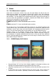
LX90xx system Version 4.0 2 February 2014 Basics 2.1 The LX9xx series at a glance LX9xx series of instrument consists of two units; the main display unit and the vario unit. Within the main display unit an integral 50-channel GPS receiver and a high brightness colour display are fitted. An integrated SD card or USB interface is used for user friendly data exchange. The main display unit is equipped with a built-in flight recorder according to the most recent IGC specification for all flights.
LX90xx system Version 4.0 Portrait or landscape orientation. Pre-loaded with worldwide terrain maps, airspace and airport databases. Unlimited number of waypoints. Unlimited number of tasks (with assigned area support). Comprehensive flight and task statistics. Display of nearest airports and out-landing fields. Unlimited number of pilots/profiles. Integrated flight recorder according to high-level IGC specification. Real-time flight optimisation according to FAI and OLC rules.
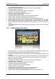
LX90xx system Version 4.0 February 2014 Flight recorder functions include an integral pressure transducer based on 1013 mbar level for altitude recording, engine noise level sensor, memory to store more than 1000 hours of flights and digital and mechanically security devices to ensure high level of security. Integrated FLARM collision avoidance system with graphic, sound and voice (optional) presentation. 2.1.
LX90xx system Version 4.0 Additional Flarm radar screen and artificial horizon. Three buttons for toggling between screen and target selection digital temperature compensated pressure sensors for altitude and airspeed inertial platform 3 axis digital +-6g accelerometer, 4 gyroscopes Smooth audio output with audio equalizer and many custom audio settings Integrated voice module 100Hz sampling rate for very fast response. Speed to fly indication.
LX90xx system Version 4.0 2.1.7 February 2014 External Options By using a RS485 bus system a wide range of optional interfaces can be easily connected to the basic configuration with minimal installation work. The LXNAV bus system can be extended easily by use of RS485 splitting units, which allow plug and play connection of optional devices.
LX90xx system Version 4.0 2.1.8 February 2014 Simulator There are two options to stay in condition and familiar with your LX90xx system. LXSim is free of charge program, which you can download from www.lxnav.com or data from the Condor PC flight simulator (www.condorsoaring.com) can be received via the RS232 port after entering suitable passwords (see Chapter 6.1.15).
LX90xx system Version 4.0 3 February 2014 Packing Lists 3.1 LX9000 (LX9070) with Flarm Option LX9000 (LX9070) main display unit V9 vario unit with V5 indicator or with V80 indicator Main power cable for main display unit Cable for vario unit SD card Barogram calibration chart GPS antenna Flarm Antenna Hex key “Inbus” 3.
LX90xx system Version 4.0 4 February 2014 Installation The main display unit is installed in an aperture 93.5 mm wide and 81.5 mm high. The vario unit and any additional vario indicators each require a standard 57 mm cut-out or standard 80 mm cut out. 4.1 Installing the main display unit Prepare the cut-out in the instrument panel according to the drilling template. Position the Main display unit in the cut-out in the instrument panel. Tighten the main display unit with attached 2.5 mm screws.
LX90xx system Version 4.0 February 2014 4.2 Panel cut-out for V9/V5 vario unit 4.3 Panel cut-out for V80 vario unit Length of screw is limited to max 6mm! 4.4 Pneumatic connection Three pressure connectors are fitted to the back of the vario unit. functions. A label shows their Pstatic means static pressure connector. Ptotal means pitot or total pressure connector. TE means total energy TE connector.
LX90xx system Version 4.0 February 2014 TE/Pstatic TE tube Pstatic Static Ptotal Pitot or Total pressure If the Ptotal and Static are connected the wrong way around there will be no integrator reading (average climb) during the flight. The main display unit is connected to 12 Volt power via the 15-pin SUB-D connector. The main display unit, vario unit and other vario indicators are connected via the RS485 bus and the connectors are labelled with “RS485” at each end.
LX90xx system Version 4.0 February 2014 4.5 Ports and Wiring Flarm external indicators, splitters … Network connector DO NOT USE IT! Flarm HF antenna GPS antenna USB memory stick Main power supply (LX9000DU wiring) 4.5.1 Flarm port 123456 Pin numbers Pin number Description 1 (output) 12V DC, to supply GPS 2 (output) 3.
LX90xx system Version 4.0 February 2014 4.5.2 Main unit wiring 4.5.
LX90xx system Version 4.0 February 2014 4.5.4 USB-D or Analog unit wiring 4.5.5 Connecting vario unit Vario unit is connected to main unit through RS485 bus. SC cable is used for external switch, for switching between climb and cruise mode. In case that SC is connected to flaps switch, VP (vario priority) is connected to switch on stick. Inputs IN1..4 are used to connect to gear switch, airbrakes, etc... 4.
LX90xx system Version 4.0 5 February 2014 System Description The main display unit can be mounted at portrait or landscape orientation. After installing the main display unit, the orientation must be defined via the Display menu (see Chapter 6.1.4). In this manual all screenshots are given for portrait orientation of the LX9000 system. However all functionality is the same in landscape orientation and on LX9070 system. 5.
LX90xx system Version 4.0 5.1.2 February 2014 Portrait orientation VOLUME selector MODE selector Ambient light sensor POWER button SD Card reader PAGE selector ZOOM selector The V9 vario unit is an indicator only and has no controls. Information displayed is controlled by the main display unit. The V80 vario unit is having three buttons to toggle between screens. More information is given in chapter 6.1.12.4 5.1.
LX90xx system Version 4.0 February 2014 5.2 Switching on the Unit After a short press of the power-on button the main display unit and vario unit will turn on and a welcome screen will appear. The first screen shows the boot loader screen followed by the Linux kernel screen and then the file system screen. The boot procedure normally takes up to 20 seconds but in the case of a firmware update or system check it can take more time.
LX90xx system Version 4.0 5.3.1 February 2014 Text Edit Control The Text Editor is used to input an alphanumeric string of arbitrary length; the picture below shows typical options when editing text. Use the bottom-right knob to change the value at the current cursor position. Press the CHAR>> button to advance the cursor to the next position. The cursor can also be moved to next position using the bottom-left knob. Rotate it clockwise to move forward.
LX90xx system Version 4.0 5.3.3 February 2014 Spin Control Spin controls are designed for numeric parameters. Rotate the bottom-right knob (page selector) to increase/decrease the selected value. The bottom-left (zoom) knob will increase/decrease the value with a different step compared to the page selector. 5.3.4 Selection Control Selection boxes, also known as combo boxes on Windows operating system, are used to select a value from list of predefined values.
LX90xx system Version 4.0 February 2014 Rotating the zoom selector changes colour transparency. Transparency is very important for fill colours which are used for airspace zones, observation zones and FAI area. If a fill colour is not transparent (0%), all other map items will not be seen through it. If a fill colour is 100% only the solid border will be drawn. Press PICK button to define colour more precisely.
LX90xx system Version 4.0 February 2014 5.4 Switching off Please use one of the following recommended methods for shutting down the LX90xx system: Method 1 Press the button with the OFF label which is displayed in navigational modes. See Chapter 6.5 for more details. A message to confirm shutdown will be shown. Method 2 Press the button with the OFF symbol for approximately 4 seconds. The OFF message will be displayed and the instrument will shut down.
LX90xx system Version 4.0 February 2014 If the request for OFF is made during flight the instrument will ask for confirmation so that the system cannot be switched off by mistake. It is important that the main display unit is switched off via software. Never power down the system using the main power switch. The main display unit is running the Linux operating system and sudden power loss may corrupt the file system.
LX90xx system Version 4.0 6 February 2014 Operating Modes The main display unit has seven modes or main menus. All of them are selectable by rotating the upper-right knob which is also called MODE selector. The diagram below shows the mode structure of the LX9000 running in portrait screen. Airport Mode, navigation and selection airports. Waypoint Mode, navigation, selection and editing waypoints. Task Mode, Navigation, selection and editing task.
LX90xx system Version 4.0 February 2014 Three main navigational modes airport, waypoint and task mode are selected by rotating the upper-right knob. All three options are similar and have similar basic navigation data screens accessed by rotating the bottom-right knob. It is possible to fully customise all three main navigational pages using the program LXStyler. This program can be downloaded from our webpage www.lxnav.com. Refer to Chapter 6.1.14 for more details.
LX90xx system Version 4.0 February 2014 6.1 Setup Mode In the setup menu users can configure the main display unit and connected devices. Turn the bottom-right knob - PAGE selector - or press the UP/DOWN arrow on the remote stick to select the appropriate setup item. Turn the bottom-left knob - ZOOM selector - or press the LEFT/RIGHT arrow on the remote stick to move faster over menu. Press the SELECT button or push middle multi-directional button on the remote stick to enter a menu.
LX90xx system Version 4.0 February 2014 6.1.1.2 Safety Altitude This setting is the altitude reserve or safety altitude and is the height that the instrument adds to the final glide altitude required so that the glider arrives over the final glide destination at the selected safety altitude. Once the safety altitude has been specified, the pilot has to keep the final glide indicator on 0 to arrive at the safety altitude. 6.1.1.3 Altitude source The system has two pressure altitude sensors.
LX90xx system Version 4.0 6.1.2 February 2014 Flight Recorder The main display unit has a built-in flight recorder fully approved by the IGC (a subcommittee of the FAI) and will produce secure flight records that are acceptable for all FAI requirements including world records. Select the recording interval and enter the pilot name. Pilot weight is important if ballast is specified in kilograms of water (see Chapter 6.1.11).
LX90xx system Version 4.0 6.1.3 February 2014 Vario Parameters* This option is used to set the following parameters: On this page the following parameters are set: Vario needle filter sets a time constant of the vario needle. The value can be adjusted between 0.1 and 5 s with step 1.0 s or 0.1 s. Default value is 1.5 s. Vario sound filter sets a time constant of vario sound. The value can be adjusted between 0.1 and 5 s with step 1.0 s or 0.1 s. Default value is 1.5 s.
LX90xx system Version 4.0 February 2014 Relative filter sets a time constant of relative vertical speed filter (also known as supper netto vertical speed). The value can be up to 20 times bigger than vario needle filter. Default value is same as vario needle filter. Netto time defines the integration period for the average netto vertical speed in seconds. The default is 20 seconds. The external switch wired to the vario unit has absolute priority and will override all other switching methods. 6.1.
LX90xx system Version 4.0 6.1.5 February 2014 Files and Transfers The Files and transfer menu is used to manage the waypoint, airspace and airport databases, recorded flights, flight declaration and PDF documents. Within a profile user can selected different airport databases, airspace and waypoint files. Selected files can be stored inside main display unit or on inserted SD card or USB stick. It is also possible to upload files from SD card or USB stick to main display unit. 6.1.5.
LX90xx system Version 4.0 February 2014 6.1.5.2 Uploading Airspace and Airports Database LXNAV distributes free of charge airport and airspace database for the whole world. The airport and airspace database is regularly maintained by LXNAV. The latest version of the database can be found on our webpage www.lxnav.com. The database is distributed as single file with .asapt extension. Copy this file to a SD Card or USB stick.
LX90xx system Version 4.0 February 2014 To delete airspace file select the airspace item and press the DELETE button. Delete action must be confirmed. Only user airspace files can be removed. Press TO USB button to copy selected airspace to USB stick. Press TO SD button to copy selected airspace to SD card. When airspace file from SD or USB is highlighted LOAD button is displayed. Press LOAD button to upload selected airspace to main display unit.
LX90xx system Version 4.0 February 2014 Press EDIT to edit data for the selected zone. Airspace type, class and altitude borders can be modified in this dialogue. 6.1.5.4 Managing Waypoints Select the Waypoints and Tasks menu item and press the SELECT button. A list of all available waypoint files will be shown on the screen. Multiple files can be selected.
LX90xx system Version 4.0 February 2014 If waypoints file from SD or USB are selected button LOAD is visible. Press the LOAD button to upload selected waypoint file to internal storage. If waypoints file from internal storage is selected button SAVE is visible. Press the SAVE button to save waypoints to the SD Card or USB stick. The save dialogue will be opened. Change the filename if required. Press TO USB for saving to the USB stick or press TO SD for saving to the SD card.
LX90xx system Version 4.0 6.1.5.6 February 2014 Managing Airports Using the LX Asapt editor LX Asapt Editor allows you to edit any LXNAV airport database distributed as asapt files. You can quickly filter the regions and find the airports you're interested in. View and edit all details of the airports, add charts, photos (from files or clipboard) and any other information you would like associated with them.
LX90xx system Version 4.0 February 2014 6.1.5.7 Managing Maps Main display unit is preloaded with terrain and vector map data for complete Earth. However it is also possible to use scanned (rasterized) maps as background of navigational screen. Next two images are showing example of scanned ICAO map and satellite imagery. The system is supporting two file formats: CMR file format provided by SeeYou software from Naviter.
LX90xx system Version 4.0 February 2014 When a map file from USB or SD card is selected, it will be available only, if SD card or USB stick is inserted in main display unit. Map files can be very big in size and can occupy a lot of space of internal storage of main display unit. Selecting maps directly from SD card or USB allows you to save space at no performance cost and create portable profiles, which can be transferred from one device to another device. 6.1.5.
LX90xx system Version 4.0 February 2014 On the screen pilot, glider and task information are shown. Press the SAVE button to save the declaration onto a SD card or USB stick. Press the LOAD button for loading. If Nano flight recorder is connected to USB port, TO NANO button will appear. Press it to transfer declaration to Nano flight recorder. Please note that not all data from the HDR file will be loaded. Glider type and class must be changed via the Polar and Glider menu (Chapter 6.1.
LX90xx system Version 4.0 February 2014 Press SELECT button again to open selected document. A document will load within few seconds. Use PAGE selector or NEXT and PREVIOUS button to move up/down through document. Use ZOOM selector to zoom current page. Use MODE selector to move left/right on the selected page. Press GOTO button to navigate to specific page. A goto dialog will be open. Use PAGE or ZOOM selector to select desired page It is also possible to set four independ bookmarks.
LX90xx system Version 4.0 6.1.6 February 2014 Graphics This dialogue allows the user to define the appearance of the map in navigational mode. Select the Graphics menu item and press the SELECT button. A submenu will open. 6.1.6.1 Terrain and Map The main display unit is pre-loaded with terrain and vector maps for the Earth. The database includes: elevation contour lines, water bodies, roads, highways, railways, big cities and a digital elevation model.
LX90xx system Version 4.0 February 2014 Colours of terrain can be changed using different terrain colour schemes. The following colour schemes are available: Mountain is default setting with colours from green to white at 2000 m. Flatland is setting where colours are changing up to 1000 m. Low contrast: same as Mountain but colours are not so intensive. High contrast: same as Mountain but colours are more intensive and from 0-100 m, white colour is used. Zebra alternating colours are used.
LX90xx system Version 4.0 February 2014 completely transparent and only the airspace zone outline will be shown. 0% means completely solid (not recommended). Image below shows example of combinations of Width and Colour property and rendering of airspace zone. Press the DEFAULT button to reset these settings back to default. 6.1.6.3 Waypoints and Airports The waypoint and airport look and feel is defined in this dialogue.
LX90xx system Version 4.0 February 2014 Code: will display the ICAO code or short name. Elevation: shows waypoint elevation. Arrival altitude shows arrival altitude taking into account current MacCready setting, safety altitude and current wind. Due to complexity of the calculation it will not take the wind profile into account. Required altitude shows how much height is needed to reach the point. Required altitude takes into account current MacCready setting, safety altitude and current wind.
LX90xx system Version 4.0 February 2014 and therefore not enough altitude to reach the target with the current glider settings. Font Style, Colour and Size define what font for terrain collision altitude and range circles. Enable Show range circles to plot range circles around aircraft symbol. Having range circles on navigational screen, it is much easier to guess distance to nearest point of interest. Range colour and range width define the way circles are rendered.
LX90xx system Version 4.0 February 2014 6.1.6.6 Task Use this dialogue to define how a task is drawn in task mode. Task colour defines the colour of task lines. Obs.zone colour defines colours for observation zones. Use the ZOOM selector knob to change transparency of area. 100% means completely transparent and only the outline will be drawn. 0% means completely solid (not recommended). When Show flown task is checked also the flown task will be drawn.
LX90xx system Version 4.0 February 2014 The colour for aircraft that are less than 100 meters below or above your current altitude is defined by the Near Colour item. When a signal from a particular aircraft is lost the aircraft remains blinking on the screen for the duration defined in the Lost device after item (default 120 seconds). After that time the aircraft symbol will not be displayed.
LX90xx system Version 4.0 6.1.7 February 2014 Sounds* In the Sounds setup page audio settings, voice settings and alarms settings for the vario unit can be modified. 6.1.7.1 Audio Settings* Basically here we can set up two types of audio; audio sound for climb mode and another for cruise mode (SC). Vario audio mode has the following options: Linear positive: sound is interrupted with silence every few milliseconds when the needle is positive; on negative side sound is linear (not interrupted).
LX90xx system Version 4.0 February 2014 SC audio mode has four modes: SC positive: sound is interrupted with silence every few milliseconds when the needle is positive; on negative side sound is linear (not interrupted). SC negative: inverse function to SC positive. SC: sound is linear and non-interrupted in full scale range.
LX90xx system Version 4.0 February 2014 Frequency and Periods define the length and pitch of alarm. Press DEMO button to play alarm sound. Change volume to define loudness of alarm.
LX90xx system Version 4.0 6.1.8 February 2014 Observation Zones This menu defines the default observation zone geometry. The following items can be chosen: start zone, turn point zone, finish zone and templates. Each type of observation zone is defined with two angles, two radii and mean bearing (Angle12). These parameters enable the creation of any known zone geometry separately for start, turn point and finish.
LX90xx system Version 4.0 February 2014 increase the radius by 0.1 of the selected distance units and the ZOOM selector knob to increase the radius by 5. If Line is not checked the Angle1 parameter will define the basic shape of the observation zone. A value of 180° means that the zone is a cylinder and 45° is the classical FAI sector. Rotate the PAGE selector knob to increase the angle by 0.5° or use the ZOOM selector knob to choose values 22.5°, 45°, 90° or 180°.
LX90xx system Version 4.0 6.1.9 February 2014 Optimization During flight the system optimises the flown path according to OLC or FAI rules. Use this dialogue to change the way instrument performs this optimisation. Number of points defines the type of optimisation. Use five for OLC optimisation. Use the value three for FAI free flight optimisation. Optimisation will not take into account the 10 km distance between turn points which is required by FAI rules.
LX90xx system Version 4.0 6.1.10.1 February 2014 Airspace Warnings Airspace warnings are the most complex ones. An airspace warning is activated by two triggers; First warning (orange) will be given when a projected position of flight for period, which is defined in the Time item, is computed to cross an airspace zone.
LX90xx system Version 4.0 February 2014 6.1.10.2 Altitude Warning Altitude warnings will be enabled if Show warning is checked. Altitude is given in MSL. Projection is calculated based on the 20 second average vertical speed and time which is defined in the Time item. If the projected altitude is greater than the set altitude, an altitude warning will be raised. Altitude warnings will be raised in all modes and dialogues just as for airspace warnings.
LX90xx system Version 4.0 February 2014 6.1.10.3 Flarm Warnings Flarm warnings will be raised only when system is receiving FLARM data from internal or external FLARM module. Using this dialogue the user can define which warnings will be shown and how they are going to be shown. There are three types of warnings: Traffic warnings will be raised once a new aircraft is detected by FLARM. Collisions will be shown every time a collision risk with an aircraft occurred.
LX90xx system Version 4.0 February 2014 6.1.10.4 Time Alarm Use this dialogue to define three independent time alarms that will be triggered at specified periods. 6.1.11 Units Use this dialogue to specify units, UTC time offset and type of ballast input. The lower-middle button will toggle all units between imperial and metric units. Glider ballast can be entered as: overload factor, which is defined as: overload Empty.glider .weight Pilot .weight Water .ballast REFERENCE .glider .
LX90xx system Version 4.0 February 2014 6.1.12 Hardware* Use this menu to define hardware properties such as total energy compensation, vario indicators layout, compass calibration, FLARM module settings, AHRS settings, NMEA output and data which will be exchanged between the rear and front display units. Some items may be greyed out when the selected option is not available. 6.1.12.1 Vario unit settings – TE compensation* All settings in this menu are related to the glider. 6.1.12.1.
LX90xx system Version 4.0 February 2014 If the digital TE option has been used TE compensation should be set to 100%. It is important to note that the method of TE compensation is set up when the instrument is installed by virtue of the pneumatic connections made to the TE and static ports. Changing the compensation type in the setup screen below WILL NOT change the method of compensation - the pneumatic plumbing has to be changed first.
LX90xx system Version 4.0 February 2014 This input wire is set open (not grounded) as a factory default on delivery. 6.1.12.1.4 Airspeed Offset Some gliders are having quite big difference between calibrated airspeed and indicated because of imperfect static ports (e.g.: Cirrus Standard). As airspeed effects wind calculation. It is possible to define an airspeed offset to improve wind calculation. Vario indicator will ignore this setting and shows not corrected airspeed. 6.1.12.1.
LX90xx system Version 4.0 February 2014 6.1.12.3 Vario indicator V5* V5 Vario indicator is having mechanical needle and colour screen with 320x240 pixels resolution on which user selectable data are displayed. Each V5 vario indicator is identified by a serial number, which is also displayed on hardware menu. Therefore literally unlimited number of vario indicators can be connected to RS485 bus and each of them can be setup separately. Description of vario indicator is shown on next picture.
LX90xx system Version 4.0 February 2014 Green T symbol represents last thermal average value. White bar displays arc between minimum and maximum vertical speed value in last 20 seconds in white colour or minimum and maximum g-load in red colour, depending on settings. Press RESET-G button to reset g-meter. Most innovative feature of V5 vario system is an upgrade. Firmware for vario unit can be easily upgraded by customer with SD card. See Chapter 9 for more details. 6.1.12.
LX90xx system Version 4.0 February 2014 Press middle button for long time to enter setup menu. In setup menu it is possible to setup graphic interface for Flarm radar screen and numeric values. Numeric screen can also be setup on main display unit. 6.1.12.5 LCD and USB-D Vario indicator This is type of the older vario indicator. An LCD vario indicator or USB-D vario indicator consists of: Needle Two numerical displays (upper and lower). Labels and indicators.
LX90xx system Version 4.0 February 2014 6.1.12.6 Flarm* On the Flarm setup page, information about built in or external Flarm are visible. Information like serial number, selected frequency, firmware version and database versions are shown. EXTERNAL FLARM If Flarm module is built in user can select operation mode. There are three different operational modes available: Power OFF - Flarm unit is switched off. Power ON - Flarm unit is switched on. Privacy ON - Flarm unit works in stealth mode.
LX90xx system Version 4.0 February 2014 6.1.12.7 Compass* When a compass is connected to the system calibration is crucial for correct operation. Refer to compass manual for more info about installation and its calibration. 6.1.12.8 Rear Seat or Front Seat In a two-seat configuration with the rear seat device it is possible to transfer selected data between the front and rear seat device. Use this menu to define which data will be automatically received from the other device.
LX90xx system Version 4.0 February 2014 When flying an assigned area task it is worth not having the task checkbox checked. This will allow one pilot to play with “what if” scenarios. Once a proper direction is found you can send the task to the other device using the SEND action in task mode. 6.1.12.9 Remote stick When a remote stick is connected to the system, it is possible to define type of remote stick via this menu.
LX90xx system Version 4.0 February 2014 6.1.12.10 AHRS When AHRS device is connected to the system or AHRS option on V9 is enabled, this menu is used to calibrate AHRS for installation error. Place you glider in levelled position and press LEVEL button. You can also modify pitch offset, if you rotate PAGE selector knob. More detailed can be pitch set using pitch offset spin control. Mode defines modes of operation of AHRS.
LX90xx system Version 4.0 February 2014 NMEA data is available also on Flarm display port on main display unit and rear display unit at 19200bps. However only Flarm data and GPS data. 6.1.12.12 Engine * Use this menu, when the system is installed into glider with engine. The current engine noise level is shown as a progress bar. If external MOP sensor is installed also MOP level will be shown. Set Threshold to define when engine is running.
LX90xx system Version 4.0 February 2014 6.1.13 Polar and Glider* Use this dialogue to enter glider polar and other properties of glider. As default polar a standard class glider is selected. Polars for most modern gliders are already prepared. Press the LIST button and a dialogue with a list of all available gliders will be shown. Select the required glider using the PAGE selector knob and press the SELECT button. All glider data will be copied from the chosen polar.
LX90xx system Version 4.0 February 2014 the pilot of the maximum take-off weight. Empty weight is weight of the glider without pilot and ballast. The overload factor is calculated as: overload Empty.glider .weight Pilot .weight Water .ballast REFERENCE .glider .weight Pilot weight is set in the Flight recorder menu (see Chapter 6.1.2). For aircraft with flap, it is also recommended to enter flap position labels and speed range for corresponded flap position.
LX90xx system Version 4.0 February 2014 to a file with the .lxprofile extension. Press the LOAD button to load a profile from a SD card or USB stick. A profile will be copied to the main display internal storage. Press the EDIT button to edit the profile name. A profile can also be locked. This option is very useful for club operation where one does not want a global club profile to be changed. When a profile is locked all settings will be read-only. Press LOCK button to lock/unlock profile.
LX90xx system Version 4.0 February 2014 If new profile is created with LX Styler, it will have default device settings. However, it is possible to copy device settings from profile to another profile. Select newly created profile as active profile. Select profile from which you would like to copy settings to active profile. Press COPY button. A confirmation dialog will open. It is also possible to export profile including all the airspace files and waypoint files.
LX90xx system Version 4.0 February 2014 6.1.16 Passwords There are several passwords which run specific procedures as listed below: 00111 displays information about the system and its sensors. 01043 will perform “Auto zero” and set indicated speed to zero. 30000 browses through installed files (use with caution). 41000 first or forced update of Flarm. 42000 update of Flarm through PC port (default). 44441 shows debug information. 55556 will enable Condor simulator input via the PC port.
LX90xx system Version 4.0 Once February 2014 Change Wind Methods, user will not be able to change methods for wind calculation. Change Page Style, it is not possible to change page layout Change Flarm Target, user can not change flarm targets names and other data for it. Use Flight Recorder menu, user can not modify flight recorder properties. Use Display menu, user can not modify display properties.
LX90xx system Version 4.0 February 2014 6.1.18 About About dialogs shown current serial number end version info od the main display unit. Use this menu, whenever you are experienced a problem with the system. If SD card is inserted into the main display unit, button TO SD will be shown. Press TO SD and a report will be saved to SD card. A report will have a name »debug_20140216_14_21_28.reprot«. Please email this report to us for further help. 6.
LX90xx system Version 4.0 February 2014 Waypoint data can be modified. Refer to Chapter 6.6.1 for more details. Press the OK button to save a marked waypoint or press CANCEL to exit without saving. Press GOTO button to navigate immediately to selected point. 6.2.2 Position Report This page shows your position report relative to an arbitrary selectable point. Use this page when you are talking to ATC. Press the REPORT button to select a report point.
LX90xx system Version 4.0 6.2.3 February 2014 Satellite Sky View Information about tracked satellites is given on this page. available a message “No satellite info” is displayed. If no satellite information is Green satellites are satellites currently being used for position determination. Three concentric circles represent satellite elevation (0, 30, 60 degrees above horizon). If a satellite is in the centre of the circles it is directly overhead.
LX90xx system Version 4.0 February 2014 Small rectangle in bottom right corner of point icons indicates that selected point is having images. 6.4 Statistics Mode The Statistics mode operates in two different ways. During flight statistical data for the current flight is shown whilst on the ground the logbook for all stored flights is displayed. 6.4.1 Logbook If a SD card or USB stick is inserted into the main display unit the user can copy a selected flight to it.
LX90xx system Version 4.0 February 2014 A map with flown path is shown and barogram. Use ZOOM selector knob to zoom in or zoom out flight. Use PAGE selector knob to move through flight. 6.4.2 Statistics during flight Main statistics page is split into two parts. In top part, last four thermals are shown. Thermal average is shown below each thermal column. Thermals are coloured based on MacCready value. Red colour means that thermal average was 0.5 m/s or more above current MacCready setting.
LX90xx system Version 4.0 February 2014 6.4.2.1 General statistics Using the PAGE selector knob the user can change the statistics subpage. There are three subpages available: Flight statistics displays data for whole flight. Dis.flown is the optimised distance. XC speed is average speed corrected for altitude difference. Average vario is used in this calculation. Task statistics displays data for the started task. Distance flown is the distance that has already been flown on the task.
LX90xx system Version 4.0 February 2014 6.4.2.3 OLC statistics Using the PAGE selector knob the user can select different optimized points. Press VIEW button to show more details for selected optimized leg.
LX90xx system Version 4.0 February 2014 6.5 Airport Mode Using the PAGE selector knob you can scroll through the pages. navigational pages available. There are several Navigational pages can be customised using LXStyler. The description below applies to the default navigational pages. 6.5.
LX90xx system Version 4.0 February 2014 rectangle will be displayed on the magenta line. The green rectangle represents the position from where you will achieve the final glide with current altitude and current MacCready setting. The yellow rectangle represents the position from where you will achieve the final glide with current altitude and MacCready zero. The relative bearing (near the top) gives advice on which direction and how much to turn in order to fly towards the selected target.
LX90xx system Version 4.0 6.5.2 February 2014 Second Navigation Page The second page is similar to the first page with additional data shown in the bottom line. The additional items are the current net vertical speed, current track, ground speed, height above ground and optimised distance. 6.5.3 Third Navigation Page The third page is a combination of first navigational page and side view. Side view is showing lateral view from glider towards selected goal.
LX90xx system Version 4.0 6.5.4 February 2014 Fourth Navigation Page The fourth navigational page is combination of FLARM radar screen and some additional altitude data. The internal pressure sensor altitude is shown as AltIGC. AltInv shows the altitude in opposite units to those defined in the Units setup. OAT is the outside temperature, Pot.
LX90xx system Version 4.0 6.5.6 February 2014 Button Actions When any of the eight buttons are pressed, the functions for the buttons are shown. If a selected button is pressed once more the selected action will take place. Press the MORE>> button to see more options. If the remote stick is available the behaviour is slightly different. When the check button is pressed on the remote stick a menu will appear instead of the button functions. By using the UP/DOWN key the pilot may select between options.
LX90xx system Version 4.0 February 2014 Flarm will display a list with all visible Flarm objects. You can select one and use it for navigational purposes. Pan will change main display unit into panning mode. In this mode user can move over map in all directions. Rot.FAI will rotate the FAI area if it is enabled. This option is not shown if it is not enabled. Event is used to log an event. The recording rate will be increased to 1 second for one minute.
LX90xx system Version 4.0 February 2014 6.5.6.1 Select an Airport There are four different methods of selecting an airport. They are called filter mode, list mode, map mode and history mode. You can toggle between these four modes by pressing the METHOD button several times. Filter mode Selecting an airport in filter mode is straightforward. Enter the first letter of the airport name using the PAGE selector knob.
LX90xx system Version 4.0 February 2014 By default the main display unit will search airports through all countries. It is possible to create a search only from selected countries. Press the COUNTRY button and a dialogue with a list of all available countries will be shown. Select the desired countries and press CLOSE. List mode In list mode airports are listed as in near mode. Press the VIEW button to change details of selected airport. Press the SORT button to change the sort order of the airports.
LX90xx system Version 4.0 February 2014 Map mode In map mode, airports are selected directly on the map. Rotate PAGE selector knob to select an airport. Details of selected airport will be drawn next to it. In upper-left corner of screen current sort method is shown. There are two possibilities, distance sort or bearing sort. Press SORT button to change it.
LX90xx system Version 4.0 February 2014 6.5.6.2 MacCready, Ballast and Bugs Settings These are probably the settings pilots use most often during flight. Press the MC/BAL button. The dialogue for MacCready, ballast and bugs will appear. Use the PAGE selector knob to modify the MacCready setting. In the middle button there is a suggestion for the MacCready setting which is based on the last four thermals.
LX90xx system Version 4.0 February 2014 Hdg/north up is a combination of heading up and north up orientation. During circling orientation will be north up otherwise Heading up. If Zoom to target is checked the zoom will be automatically adjusted so that the target point is always visible. Maximum zoom is 200 km and minimum zoom is 1 km. The check boxes will turn on or off the following items: Map – complete map is turned on/off. Terrain – only terrain is turned on/off.
LX90xx system Version 4.0 February 2014 Press button MEM 1 for a long time. A message “Options stored to memory (1)” will be displayed and the settings are stored. Change the settings a little bit. Press button MEM 2 for long time. A message “Options stored to memory (2)” will be displayed and the settings are stored to memory location 2. Now short pressing of MEM 1 will invoke the saved settings from memory 1. 6.5.6.4 Wind The main display unit constantly calculates winds using four different methods.
LX90xx system Version 4.0 February 2014 The user can also disable or enable a particular wind method. It is recommended to have all methods enabled. Once the wind is modified to suit your needs press the OK button to accept the wind values. The dialogue will exit automatically. If the CANCEL button is pressed the wind dialogue will be closed without applying the changed values. 6.5.6.5 Airspace The Airspace dialogue shows a list of airspace zones in the vicinity of your position.
LX90xx system Version 4.0 February 2014 Waypoint data can be modified. Refer to Chapter 6.6.1 for more details. Press the OK button to save a marked waypoint or press CANCEL to exit without saving. Press GOTO button to navigate immediately to selected point. 6.5.6.7 Team The Team feature will help you find or hide your teammate. It lets you share your position with other pilots and even encrypt this information so that your competitors won't be able to decode it. To use it press TEAM button.
LX90xx system Version 4.0 February 2014 drawn next to it. You can select as many favourites as you want. Depend on Flarm graphics settings (See chapter 6.1.6.7) only favourites will be displayed on the map. One target can be selected as an active target. Press ACTIVE button to make target as active one. A blue bulls-eye will be plotted next to it. Team navboxes will show distance and bearing to this target. Press the GOTO button to start navigation to this Flarm position.
LX90xx system Version 4.0 February 2014 A blue cross will be plotted over the screen with info box for given cross position. Move cross up and down on map using PAGE selector knob. Move cross left and right using MODE selector knob. Turn ZOOM selector knob to zoom map. If remote stick is being used move jogger to move map. Press INFO button to change information for given position of cursor.
LX90xx system Version 4.0 February 2014 6.5.6.11 Style Use this option to modify layout of navigational page. See chapter 7 for detailed explanation.
LX90xx system Version 4.0 February 2014 6.6 Waypoint Mode Waypoint mode is very similar to airport mode. In this mode the user can navigate to waypoints from selected files. In addition to the options in airport mode there are three additional options: Edit waypoint, new waypoint and delete waypoint. Navigational pages can be customised using LXStyler. The description below applies to the default navigational pages.
LX90xx system Version 4.0 February 2014 Off will switch off the instrument. The message LX9000 switching off will be displayed. 6.6.1 Editing Waypoints Press the EDIT button. The Edit dialogue will be open with details of the selected waypoint. There are two possibilities to enter a position. You can modify latitude and longitude to define a position of the point or press the DIS/BRG button to enter the position as distance and bearing to a selectable point.
LX90xx system Version 4.0 6.6.2 February 2014 New Waypoint Select this option if you want to add new a waypoint to the active waypoints file. If no waypoints file is selected a new waypoint file will be created with name default.cup. A message “Do you want to copy from airport?” is displayed first. Press YES if you would like to copy it from the Airports database. An airport select dialogue will be opened. Select the airport you wish to copy. If none is selected a blank edit dialogue is opened.
LX90xx system Version 4.0 February 2014 6.7 Task Mode Task navigation mode is used for task manipulation. Navigation in this page is exclusively to the selected turn point of the declared task. A task can be created only from stored waypoints or airports. A task can also be loaded from stored tasks. A task can will be saved to an active waypoint file (see Chapter 6.1.5.4 for details how to set an active waypoint file). A task used for navigation will also be declared in the IGC file.
LX90xx system Version 4.0 February 2014 The third page is designed for tasks with time limits which are in most cases going to be assigned area tasks. Three new symbols are added: Tsk.Sp which is task speed achieved up to this moment. tReq.Sp which is the required speed to task completion. It is calculated as the remaining task distance divided by the remaining time. tRemain: indicates the remaining task time. The fourth page is identical to the fourth page of the airport or waypoint mode.
LX90xx system Version 4.0 February 2014 Wind will open a dialogue where wind changes with altitude are shown, wind can be set and methods for wind calculation are shown. See Chapter 6.5.6.4 for more details. Airspace shows a list of airspace zones in the vicinity of the current position. See Chapter 6.5.6.5 for more details. Pan will change main display unit into panning mode. In this mode user can move over map in all directions. Rot.FAI will rotate the FAI area if it is enabled.
LX90xx system Version 4.0 February 2014 STARTS will open new dialogue, where user can enter multiple start points. Press LOAD to load the task from the active waypoint file. Press SAVE button to store the task to the active waypoint file. This task can later be loaded from the active waypoint file. TO NANO button will be available, if Nano flight recorder is connected to the main display unit. Press this button to send declaration to it. INVERT action will invert the complete task.
LX90xx system Version 4.0 February 2014 If you would like to change source for selection of waypoints, which are used to create task, press SOURCE button and select appropriate source. There are three options available: active waypoint file, all selected waypoint files or waypoint files and airports. Sometimes, it is easier to see list of all waypoints. Press LIST button to change selection method to list mode. Press FILTER button to go back to this mode.
LX90xx system Version 4.0 February 2014 Press VIEW button to change view from list to detailed list view. In detailed list view also latitude and longitude for selected task point are given. Press VIEW button once more to enter map edit mode. 6.7.2.1 Map mode In map mode, it is possible to create task on map. Use MODE selector knob to move grey cross left or right and PAGE selector knob to move up and down. Turn ZOOM selector knob to zoom. Move cross to task point to pick it and move it around.
LX90xx system Version 4.0 6.7.3 February 2014 Multiple start points On some competitions, multiple start points are used for start. Press STARTS button to open multiple starts dialog. First start point will be grey out. This is point, which is defined in task. Add as many start points as required. Later it is possible to cycle through start points with CYCLE button. 6.7.4 Modifying Zones Now it is time to modify the observation zones. Select a point and press the ZONE button.
LX90xx system Version 4.0 February 2014 Fixed: mostly used for assigned areas. Next: orients the observation zone in direction of the outgoing leg. This is usually used for start. Prev: orients the zone in direction of the incoming leg and is usually used for the finish. Start: orients the sector always towards the start. If the Line box is checked the sector will become a line type of observation zone. The Radius1 parameter defines half the width of the line length.
LX90xx system Version 4.0 February 2014 and finish zone. Start out the top will enable detection of start, when leaving start sector from the top of it. The Navigate to nearest point option is very useful and actually a must if a finish cylinder is used with a significantly large radius. Enabling this option will calculate the final glide to the edge of the cylinder rather than to the centre of the cylinder.
LX90xx system Version 4.0 February 2014 The lower number indicates at what altitude you will reach start altitude. A negative value indicates you are going to be there below the required start altitude. The arrival altitude to start is not based on MacCready, the glider nor the wind settings. It is calculated based on energy difference during flying straight. This gives a very precise estimate at what altitude you will arrive at the start.
LX90xx system Version 4.0 February 2014 If the task already exists in the active waypoint file the message “Task is already saved!” is shown. 6.7.7 Loading a Task It is possible to load a task from the stored tasks within the active waypoint file. Select the LOAD action within task mode. A dialogue with a list of all stored tasks will be shown. Total task distance, task description and task points are shown for each task stored.
LX90xx system Version 4.0 February 2014 Delta time is the difference between the remaining time and time of arrival. If it is negative you will arrive back home too soon and if it is positive you will arrive too late. Keep in mind that the time of arrival can be calculated using different methods which are found in the QNH and RES setup (see Chapter 6.1.1). A point is moved using the lower two knobs. Press the DIS/BRG or LON/LAT button to toggle between the two methods of moving the point.
LX90xx system Version 4.0 7 February 2014 Navigational page layout On the main display unit navigational page layout can be completely modified and customized to match user preferences. There are two possibilities for page customization. LX Styler program, a free program for Windows operating system, which can be downloaded from our webpage www.lxnav.com. (See LX Styler manual for more details) LAYOUT option on main display unit, where you can modify selected navigational page.
LX90xx system Version 4.0 February 2014 symbol. They are showing also direction of resizing. In information text-box height and width of symbol are given. GLOBALS will open dialog, where global properties of navigational page are set. Use this dialog, if you want to change font properites for all the symbols at once. CLOSE action will close page customization mode and return to normal navigational mode. 7.1 Global styles for navigational page Press GLOBALS button to open dialog for global styles.
LX90xx system Version 4.0 February 2014 Orientation symbol is showing direction of north. Final glide symbol shows current MacCready setting and information about required altitude. It is highly recommended to include this symbol on navigational page. Battery displays status of power supply. GPS Status indicates status of gps signal. Wind Arrow shows direction of wind relative to map orientation Zoom symbol defines scale of map.
LX90xx system Version 4.0 February 2014 AltInv MSL in other units Rwy.Len Target runway length Arrival Arrival altitude on target sBrg Bearing to zone center ArrMc0 Arrival altitude for Mc=0 sDis Distance to zone center As.
LX90xx system Version 4.0 February 2014 the glide path. Chevrons show the position relative to the required glide path in percent. One arrow means 5% above or below final glide. The middle number is the current MacCready setting. In task mode it is prefixed with the letter T, A, B, G, S or AG. See chapter 8.2.1 for detailed explanation of this mode. Sometimes there will be another number above MacCready which is used for arrival over terrain.
LX90xx system Version 4.0 7.2.6 February 2014 Flap tape® Flap tape displays current and required flap position. Scale of flap tape matches airspeed tape. Magenta pointer shows required flap settings. White pointer shows selected flap position. Selected flap position band is coloured with green colour, when matching flaps are set. When wrong flaps are set, then selected flap band will be coloured red.
LX90xx system Version 4.0 8 February 2014 Flying with the System To get the best out of the system it is important that some preparation is done prior to takeoff. Trying to configure the instrument or set a task while flying is very hazardous especially in a competition. At the least, it could spoil your whole day! Pre-flight preparation will ensure that the flight will be both safe and enjoyable. 8.1 On the Ground 8.1.1 Power on Procedure Press the power-on button.
LX90xx system Version 4.0 8.1.3 February 2014 Set Elevation and QNH This setting is crucial for final glide calculation: therefore pay careful attention to it. The instrument will offer elevation from the terrain database based on current latitude and longitude. Elevation will mostly be within few meters from the current elevation. Use the PAGE selector knob to fine-tune the elevation. If the elevation is unknown and the QNH pressure is known you should NOT press button QNH.
LX90xx system Version 4.0 February 2014 Use the PAGE selector knob to modify the MacCready setting. Refer to Chapter 6.5.6.2 for more details. It is also highly recommended to check the safety altitude setting. Refer to Chapter 6.1.1 to find out how to define the safety altitude. 8.1.
LX90xx system Version 4.
LX90xx system Version 4.0 February 2014 Usually a task sheet with observation zone definitions matching the system observation zone definition will be given. An example of a task sheet is shown on the previous page. However when an assigned area is defined only with two radials and two radii some calculation must be accomplished. Let us assume an assigned area defined as: Radial1=30°, Radial2=70°, Min.radius=50 km and Max.
LX90xx system Version 4.0 February 2014 Ground speed and pressure altitude are also shown in the message. At the bottom two buttons are displayed. Use the CLOSE button if this was not a valid start and you want to remove the message from screen. If message is removed it will appear again next time you leave the start zone. If you press the START button navigation will be advanced to the first turning point. There is no need to press START inside the start observation zone.
LX90xx system Version 4.0 8.2.3 February 2014 Over Turn Point When a turn point observation zone is reached the message “Inside zone” will be displayed and the task will auto advance to the next turn point if the Auto next option was selected (see Chapter 6.7.4). When the Auto next option was not selected the message NEXT will be displayed. Press the associated button to advance to the next turn point.
LX90xx system Version 4.0 February 2014 If NEXT is pressed the task is advanced to the next turn point. When flying in an assigned area it is NOT important when you will advance to next turn point. The system is always taking into account the most optimal fix inside the assigned area for the total distance calculation. 8.2.5 Moving Point Inside Assigned Area If at least one observation zone is defined as an assigned area, it is possible to move the point within this area.
LX90xx system Version 4.0 8.2.6 February 2014 Task Finish When reaching final glide, a message task on final glide will be displayed. The main display unit will also warn you, when you are two minutes to finish. On entering the finish zone the task stops automatically and a message will be displayed. If you want to fly a new task without landing, load the new task and press the RESTART button.
LX90xx system Version 4.0 February 2014 If a SD card or USB stick is currently inserted into the main display unit the flight will automatically be copied to it. Please use regular methods to power down the system. See Chapter 5.4 for details. It is important that the system is switched off via software. Never power down the system using the main power switch. The main display unit is running the Linux operating system and sudden power loss may corrupt the file system.
LX90xx system Version 4.0 9 February 2014 Firmware Update Firmware updates of the main display unit, vario unit or vario indicator can be easily carried out using the SD Card. Please visit our webpage www.lxnav.com and send us a request for the firmware update. You can also subscribe to a newsletter to receive news about the system automatically. 9.1 Updating main display firmware We will send you an update file and update code. The update code is a string six letters long and the update file has the .
LX90xx system Version 4.0 February 2014 Please note that the update file and update code are a matching pair only applicable to a particular serial number. Once the update file is verified the main display unit will reboot and the new firmware is ready for use. 9.2 Updating vario unit or Vario indicator Start the system and go to the Setup->Password menu option. Enter password 89891 and press ENTER. The system will automatically search for an update file.
LX90xx system Version 4.0 February 2014 10 IGC Barograph Recalibration Procedure The main display unit has an additional pressure sensor for altitude recording. To comply with IGC procedures this sensor has no external pneumatic connection. To carry out the barograph calibration procedure it is necessary to remove the instrument from the glider and place it in a vacuum chamber. The procedure is as follows: Switch the instrument ON and wait some minutes (straight line on the barogram beginning).
LX90xx system Version 4.0 February 2014 11 Options 11.1 Flarm Before using Flarm it is highly recommended to read the Flarm user manual which can be downloaded from www.flarm.com. Respect all limitations listed in this document. Flarm is a collision avoidance system developed by Flarm Technologies from Switzerland. The Flarm module consists of following main parts: GPS receiver, microcontroller unit, radio transceiver pressure altimeter and optional an external indicator.
LX90xx system Version 4.0 February 2014 The Flarm external display is a small unit and can be placed anywhere on the instrument panel. To fix the device, use self-adhesive tape on the back of the device. For position on the top of the instrument panel a suitable box is available. 11.1.2 Flarm Update Procedure The Flarm is updated via the SD card. From the Flarm web (www.flarm.com) Support / Updates page download the appropriate file and copy to the SD card (e.g. flarm_407.fw).
LX90xx system Version 4.0 February 2014 In the Files and Transfer menu select the Update Databases menu item. Select the FlarmNet file and wait until the update completes.
LX90xx system Version 4.0 February 2014 11.2 Rear Seat Device In two-seat gliders it is possible to install the rear seat device. The rear seat device looks almost identical to the main display unit. However inside the device there is no GPS or Flarm module. The rear seat device must be connected only to the main display unit via the RS485 bus system.
LX90xx system Version 4.0 February 2014 Data is divided into two groups; flight parameters and navigational data. If a specific value is checked this value will be automatically be received from the other device. Check MacCready, Ballast and/or Bugs to receive the current MacCready value, current ballast setting or bugs from the other device. If Waypoint is checked a new waypoint target will be automatically assigned when the user changes the waypoint target on the other device.
LX90xx system Version 4.0 February 2014 11.3 ADSB-Receiver (TRX-1090) It is possible to connect to the system with build in Flarm an ADSB-receiver TRX-1090 from Garrecht Avionics (www.garrecht.com). TRX-1090 can only be connected to the system with integrated Flarm option. The TRX-1090 has been developed to upgrade the FLARM collision avoidance system, which is installed in more than 13.000 aircraft worldwide.
LX90xx system Version 4.0 February 2014 Select Port2 tab and change Baud rate to 19200bps. The LX90xx system and TRX-1090 are now ready for operation. should see the TX sign and number of received objects. On the info page you 11.3.1.2 Connecting TRX-1090 to the system Disconnect cable from the Flarm external display and connect the free cable to Port4 on the TRX-1090. Use the LX9000-TRX cable (not-included, must be ordered separately) and connect it between PORT2 and PC port on the main display unit.
LX90xx system Version 4.0 February 2014 On main display unit side LX5FLARM is connected to 5 pin rounded connector. On the other side of LX5FLARM cable is 6 pin standard IGC RJ12 plug connector, which is plugged into Flarm/Power Flarm port. Using improper type of cable may harm your display unit or Flarm/Power Flarm units. 11.
LX90xx system Version 4.0 February 2014 11.6 Remote Control Remote stick is available in three different versions. Normal one, with red starter button or with trim switch The stick is available also in various diameters: 18 mm, 19.3 mm, 20.3 mm, 24.4 mm and 25.4 mm. All necessary electronics is built into the top of the stick. The four coloured wires from the bottom must be connected to RS485 splitter. Additionally two shielded cables are used for speed to fly command and push to talk button.
LX90xx system Version 4.0 February 2014 11.6.1 Functions Function button Mode Right Joystick Push=Enter /OK Blue dot button / mode left Cancel / close Push to talk Remote stick has six push buttons and on multi-directional button in the middle. Move multidirectional button left and right to zoom in and out. Move it in up and down direction to select different page of to move on menu. Press it to select and item or to invoke a menu in navigational mode.
LX90xx system Version 4.0 February 2014 11.7 Installation Remote stick is connected to RS485 bus through RS485 splitter. correct coloured wire to pin, which is marked with same colour. Be careful to connect PTT wires are connected to radio push to talk input and SC wire is connected to Speed to fly input of vario unit. Do not forget to set the speed command input setting to TASTER (see Chapter 6.1.12.1).
LX90xx system Version 4.0 February 2014 11.8 Flap sensor® The flap encoder is connected to the system via the RS485 bus. It is physically mounted near the flap mechanism. The flap encoder is very sensitive and accurate and can detect very small movements. Please refer to flap sensor manual for details about installation. For configuration on the main display unit see Chapter 6.1.12.13. 11.9 Secondary Vario Indicators An unlimited number of secondary vario indicators can be connected to the system bus.
LX90xx system Version 4.0 February 2014 12 Revision History September 2010 April 2011 September 2011 February 2014 Initial release of owner manual based on LX9000 manual version 2.3 Corrections to English language text. V5 vario unit Updates for firmware version 2.6. Added AHRS section. Updates for firmware version 4.0.