
Operation Manual

LX90xx system Version 4.0 February 2014
Page 89 of 151
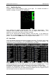
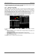
rectangle will be displayed on the magenta line. The green rectangle represents the
position from where you will achieve the final glide with current altitude and current
MacCready setting. The yellow rectangle represents the position from where you will
achieve the final glide with current altitude and MacCready zero.
The relative bearing (near the top) gives advice on which direction and how much to turn in
order to fly towards the selected target. In the above example we should turn right 21°.
In the lower left corner of screen a wind symbol is displayed. The arrow indicates the
wind direction relative to the map orientation. Wind direction and wind speed are
numerically presented below the arrow.
Zoom scale is displayed in bottom right corner of screen. A distance of drawn zoom symbol
is plotted above the scale. If there is a letter “a” written next to distance scale, it means,
scale of map will automatically adapt to goal.
In the bottom row several items are displayed. Thermal shows the last thermal average,
Brg is the bearing to the selected target, Dis is the distance to the target and Alt is the
current MSL altitude.
The last two numbers (reqE and E) show the required glide ratio to the target. In the
above example the required glide ratio is infinitive and current glide ratio is also infinitive.
The current glide ratio is calculated over the last two minutes of flight.
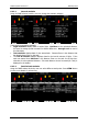
6.5.1.1 Final Glide Symbol
The final glide symbol is a complex symbol. The bottom number (-682 in the above
example) shows your predicted arrival altitude. Negative numbers indicate that you are
below the glide path and positive numbers indicates you are above the glide path. In the
above example the glider is below the glide path. Chevrons show the position relative to the
required glide path in percent. One arrow means 5% above or below final glide. In the
example more than 25% below glide path is shown.
The middle number is the current MacCready setting. In task mode it is prefixed with the
letter T, A, B, G, S or AG. See chapter 8.2.1 for detailed explanation of this mode.
Sometimes there will be another number above MacCready which is used for arrival over
terrain. If we are on final glide to a selected target but between it and the current position
there is a terrain, which cannot be crossed without more height, then this number will give
you an estimate, how much you have to climb, to pass over the terrain. A red rectangle will
also be shown on the magenta line indicating the point of potential collision.
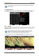
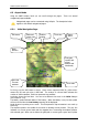
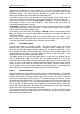
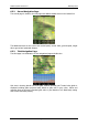
6.5.1.2 Thermal Assistant
During thermaling the wind symbol will also shows the thermal assistant. The thermal
assistant continuously analyses the thermal whilst circling. The sizes of the dots indicate the
strength of the thermal. Big dots mean stronger lift at that point. On the left or right side
of the circle a small airplane symbol is shown. This airplane indicates your position. A black
dot indicates the thermal maximum. The pilot should extend the circle when the black dot is
about 60° away from glider. This value varies and depends on turn rate of the glider and
type of thermal. All other dots are coloured based on the MacCready setting. Red colour
means values above MacCready, blue values below MacCready and yellow dots represents
lift about the same strength as the MacCready setting.
This colour scheme gives us hints about a thermal at glance. If most of dots are red we
should consider increasing the MacCready value; if most of dots are blue we should consider
decreasing the MacCready setting.