
User's Manual

14 Getting Started
MX3X Reference Guide E-EQ-MX3XRG-H
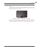
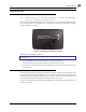
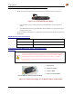
Figure 1-14 Connecting the Power Supply to the MX3P Endcap Power Jack
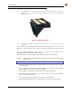
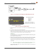
DIAGRAM IS NOT TO SCALE
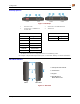
Power Supply Dimensions
Length 9.25”
Height 2.5”
Width 4.7”
Mounting hole center Width: 3.5”
Mounting hole center Length: 8.75”
Figure 1-15 Vehicle Power Supply Footprint
1. If the mobile device is in the cradle, it can be either On or in Suspend Mode during this
process.
2. Turn the Power Supply toggle switch to the Off position.
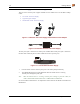
3. While observing the fuse requirements specified above, connect the power cable as close as
possible to the actual battery terminals of the vehicle. When available, always connect to
unswitched terminals in the vehicle fuse panel, after providing proper fusing.
IMPORTANT:
For uninterrupted power, electrical supply connections should not be made at any point
after the ignition switch of the vehicle.
4. Route the cable the shortest way possible. The input cable from the connection to the battery
is rated for a maximum temperature of 60°C (140°F). When routing this cable it should be
protected from physical damage and from surfaces which might exceed this temperature.
Additionally do not expose the cable to chemicals or oil that may cause the wiring insulation
to deteriorate.
Note: If the vehicle is equipped with a panel containing Silicon Controlled Rectifiers
(SCR's), avoid routing the power cable in close proximity to these devices.
Always route the cable so that it does not interfere with the operator's safe operation and
maintenance of the vehicle.