
User's Manual
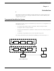

Table Of Contents
- 95 Series RFID System User’s Guide
- Table of Contents
- List of Figures
- Preface
- Introduction
- Reader R95 Installation and Connections
- Exciter E95 Installation and Connections
- Power Supply TRM95 Installation and Connection
- Configuration and Operation
- Before You Begin
- General Procedure Rules
- Setting Up the Reader/PC Connection
- Reader’s Power-up Sequence
- Learning Procedure (Optional)
- Resetting the Reader
- Checking the Reader’s Basic Parameters
- Setting Up the Exciter’s Address
- LF Transmitter Output
- Configuring the Reader
- Setting Up the Carrier Threshold
- Setting Up the Exciter’s Test-Tag
- Setting Up the Real Time Clock
- Configuring the Reader’s Application Parameters
- Configuring the Reader’s Network Parameters
- Storing the Reader’s Configuration
- Reader - Final Setup
- 95 Series RFID System - Final Test
- Programming and Testing the Transponder T95
- Troubleshooting
- Specifications
- Transponder T95 Messages
- Excitation Modes
- Reader Software Upgrade Procedure
- Glossary
- Index

95 Series RFID System Configuration Principles
Introduction 1-3
By using a RFID system comprising of a population of Transponders and strategically
placed Readers and Exciters, you can electronically monitor the path of test letters
through the collection and delivery process, particularly at points between Postal
administrations and their agents.
Each probe letter includes a RFID Transponder bearing a unique identification. The
probe letters are posted, sorted, and delivered in the same way as normal letters. As
they pass pre-determined points en-route (Reading Points/identification zones), the
Transponders are identified. The collected information is then read and stored on
local computers. This information is downloaded on demand to a Central
Management System (CMS).
The Postal RFID System includes the following main specific equipment:
• Transponders T95 carrying the identification data
• Exciters E95 to generate an electromagnetic field that excites the Transponder
T95
• Readers R95 to receive data transmitted by the Transponder T95 and to relay this
information via the RS-485 interface to the main computer
• Power Supply TRM95 to power Readers R95 and Exciters E95 from the local AC
main supply.
IMPORTANT Each piece of equipment can have different commercial models (Transponders T95B,
T95C, TRD95, and TBC95), but they behave similarly. This manual refers to them as
a generic T95 model.
95 Series RFID System Configuration Principles
The RFID System is highly configurable, allowing you to setup operational
parameters for the optimum performance of the System. The sections that follow give
some basic information regarding the 95 Series RFID System configuration. A
detailed description of the configuration, with a focus on an IPC implementation, is
giveninChapter5,Configuration and Operation.
Communication Links There are several communication links between the components of the 95 Series RFID
System. As a general rule, all equipment attached to a particular link must have the
same parameters settings to communicate. Some communication links can be
configured, others, however, have fixed configurations, as follows:
• Reader-to-Transponder: excitation (LF=125.0 kHz) - configurable;
writing (infrared) - fixed configuration.
• Transponder-to-Reader (UHF-433.92 MHz) - configurable.
• Reader-to-Exciter and Exciter-to-Reader (RS485_COM, RS485_SGN) - fixed
configuration.
• Reader- to-Main PC and Main PC-to-Reader (RS-232 or RS-485) - configurable.
System Parameters Parameters controlling the 95 Series RFID System’s configuration are logically
organized in groups. For a detailed explanation on the meaning and usage of the
parameters, refer to the 95 Series RFID System Reference Guide. The parameters