
User's Manual
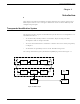

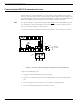
Table Of Contents
- 95 Series RFID System User’s Guide
- Table of Contents
- List of Figures
- Preface
- Introduction
- Reader R95 Installation and Connections
- Exciter E95 Installation and Connections
- Power Supply TRM95 Installation and Connection
- Configuration and Operation
- Before You Begin
- General Procedure Rules
- Setting Up the Reader/PC Connection
- Reader’s Power-up Sequence
- Learning Procedure (Optional)
- Resetting the Reader
- Checking the Reader’s Basic Parameters
- Setting Up the Exciter’s Address
- LF Transmitter Output
- Configuring the Reader
- Setting Up the Carrier Threshold
- Setting Up the Exciter’s Test-Tag
- Setting Up the Real Time Clock
- Configuring the Reader’s Application Parameters
- Configuring the Reader’s Network Parameters
- Storing the Reader’s Configuration
- Reader - Final Setup
- 95 Series RFID System - Final Test
- Programming and Testing the Transponder T95
- Troubleshooting
- Specifications
- Transponder T95 Messages
- Excitation Modes
- Reader Software Upgrade Procedure
- Glossary
- Index

95 Series RFID System Configuration Principles
Introduction 1-5
For the software reset, press the RESET button on the Motherboard MBD95 twice, or
type the command:
:RESET<Enter>
The software reset resets the Microcontroller. The hardware reset resets the
Microcontroller and runs a complete memory test.
Exciter Address When an Exciter E95 is part of a network, it must have an unique address. You can
set the Exciter’s address in a binary format between 0001 and 1110, using the S1
switch on the EXT95SC board.
Once an address is assigned, the Exciter will only process commands with a matching
address field. In this way, you can direct commands in the network to a specific
Exciter E95.
Note Addresses 0000 and 1111 are reserved for special modes of operation.