
User's Manual
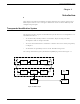

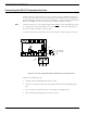
Table Of Contents
- 95 Series RFID System User’s Guide
- Table of Contents
- List of Figures
- Preface
- Introduction
- Reader R95 Installation and Connections
- Exciter E95 Installation and Connections
- Power Supply TRM95 Installation and Connection
- Configuration and Operation
- Before You Begin
- General Procedure Rules
- Setting Up the Reader/PC Connection
- Reader’s Power-up Sequence
- Learning Procedure (Optional)
- Resetting the Reader
- Checking the Reader’s Basic Parameters
- Setting Up the Exciter’s Address
- LF Transmitter Output
- Configuring the Reader
- Setting Up the Carrier Threshold
- Setting Up the Exciter’s Test-Tag
- Setting Up the Real Time Clock
- Configuring the Reader’s Application Parameters
- Configuring the Reader’s Network Parameters
- Storing the Reader’s Configuration
- Reader - Final Setup
- 95 Series RFID System - Final Test
- Programming and Testing the Transponder T95
- Troubleshooting
- Specifications
- Transponder T95 Messages
- Excitation Modes
- Reader Software Upgrade Procedure
- Glossary
- Index

Before You Begin
Reader R95 Installation and Connections 2-1
Chapter 2
Reader R95 Installation and Connections
This chapter explains how to:
• Install the Reader Module Assembly into the Reader’s enclosure
• Connect the serial interfaces and the power supply
• Set the jumpers for interfaces
• Connect the external devices to the Reader R95 (optional)
Before You Begin
Before installing the Reader:
• Read Chapter 4, Setup Guidelines in the 95 Series RFID System Technical Guide.
• Have at your disposal, the complete approved documentation describing the RFID
System configuration, equipment location, and wiring distances between the
equipment (see the Site Survey Documentation).
• Check whether the Reader’s enclosure, power supply and interconnection cable
with the main PC are installed on the site according to the approved
documentation (see the Site Survey Documentation).
• Set a color table for each interface and power supply cables. Pay special attention
to the interface terminals, cable shields, and the ground wires.
• Check whether the Reader’s Kit (P/N 600418) is complete according to the product
shipping list.
Mechanical Assembling
To assembly the Reader R95, refer to assembly drawing M900199 in Chapter 8, Power
Supply Assembly Drawings, and complete the following steps:
1. Install the RF assembly cables (P/N 50053) on the Reader’s enclosure using a
13 mm fix key.
2. Install the Reader R95 Module Assembly (P/N 500048) into the Enclosure Base
and secure it using the four 6-32x1/4 inch screws from the Reader R95 Kit. See
drawing M900120.
3. Connect the two RF cables to the RF connectors on the Receiver Board CRM95
(middleboardoftheReaderModuleAssembly).