
User's Manual
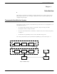
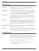

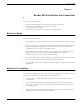
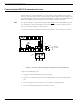
Table Of Contents
- 95 Series RFID System User’s Guide
- Table of Contents
- List of Figures
- Preface
- Introduction
- Reader R95 Installation and Connections
- Exciter E95 Installation and Connections
- Power Supply TRM95 Installation and Connection
- Configuration and Operation
- Before You Begin
- General Procedure Rules
- Setting Up the Reader/PC Connection
- Reader’s Power-up Sequence
- Learning Procedure (Optional)
- Resetting the Reader
- Checking the Reader’s Basic Parameters
- Setting Up the Exciter’s Address
- LF Transmitter Output
- Configuring the Reader
- Setting Up the Carrier Threshold
- Setting Up the Exciter’s Test-Tag
- Setting Up the Real Time Clock
- Configuring the Reader’s Application Parameters
- Configuring the Reader’s Network Parameters
- Storing the Reader’s Configuration
- Reader - Final Setup
- 95 Series RFID System - Final Test
- Programming and Testing the Transponder T95
- Troubleshooting
- Specifications
- Transponder T95 Messages
- Excitation Modes
- Reader Software Upgrade Procedure
- Glossary
- Index

Connecting the RS-232 Communication Line
2-2 Reader R95 Installation and Connections
Connecting the RS-232 Communication Line
The RS-232 data transmission line is used for point-to-point communication with a
local PC. This connection can be used during the 95 Series RFID System configuration
or troubleshooting. The RS-232 connector and jumper are located on the Motherboard
MBD95.TheMBD95isthebottomboardoftheReaderModuleAssembly.
Note For the RS-232 line, use specially designed cables only
, such as, BELDEN type 8102,
or a standard PC cable used for RS-232 interconnections. For more information, see
the 95 Series RFID System Technical Guide.
To connect the RS-232 communication line to the Reader, refer to Figure 2-1 below.
Figure 2-1: Connections and Jumper Settings for the RS-232 - PC Communication Line
Complete the following steps:
1. Unplug terminal block TB8 from connector TB7.
2. Connect the communication wires TX, GND and RX to the corresponding TB8
pins.
3. Place the jumper P2 between pins 1-2 of J2 (RS-232 configuration).
4. Plug terminal block TB8 back into connector TB7.
M
a
t
h
e
r
b
o
a
r
d
M
B
D
9
5
Controller CTL95
TX
RX
1
RS232
TB8
TX GND RX
J2
P2
RS232
RS4852
Interface
Selection