
User's Manual
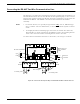
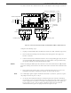
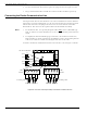
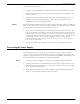
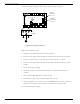
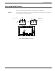

Table Of Contents
- 95 Series RFID System User’s Guide
- Table of Contents
- List of Figures
- Preface
- Introduction
- Reader R95 Installation and Connections
- Exciter E95 Installation and Connections
- Power Supply TRM95 Installation and Connection
- Configuration and Operation
- Before You Begin
- General Procedure Rules
- Setting Up the Reader/PC Connection
- Reader’s Power-up Sequence
- Learning Procedure (Optional)
- Resetting the Reader
- Checking the Reader’s Basic Parameters
- Setting Up the Exciter’s Address
- LF Transmitter Output
- Configuring the Reader
- Setting Up the Carrier Threshold
- Setting Up the Exciter’s Test-Tag
- Setting Up the Real Time Clock
- Configuring the Reader’s Application Parameters
- Configuring the Reader’s Network Parameters
- Storing the Reader’s Configuration
- Reader - Final Setup
- 95 Series RFID System - Final Test
- Programming and Testing the Transponder T95
- Troubleshooting
- Specifications
- Transponder T95 Messages
- Excitation Modes
- Reader Software Upgrade Procedure
- Glossary
- Index

Connecting the RS-485 Four-Wire Communication Line
2-4 Reader R95 Installation and Connections
Complete the following steps:
1. Unplug terminal blocks TB4 and TB6 from connectors TB3 and TB5 respectively.
2. Run the incoming and outcoming RS-485 cables through the cable grips into
Reader’s enclosure.
3. Connect a short piece of wire between pins A and Y of terminal block TB4 (or
TB6). Connect another wire between pins B and Z of terminal block TB4 (or TB6).
4. Connect the two-wire communication line to the corresponding pins A and B of
terminal block TB4 (or TB6). Connect the cable shield to the pin marked with the
ground symbol on terminal block TB4 (or TB6).
Caution Before you install the RFID System, label the 2 wires on the RS-485 line A and B.
Keep this naming convention for all connections made on this RS-485 communication
line.
5. Place jumpers P3 between pins 2-3 of J3 and P4 between pins 2-3 of J4 to set the
half-duplex mode for the RS-485 interface.
6. Set the RS-485 communication line terminating load. The ends of a multidrop
network line can be easily identified, because only one RS-485 cable is connected
to that equipment. To connect a 120 ohm terminating load, place the jumper P1
between pins 1-2 of J1. For any other equipment connected to this RS-485
communication line, place the jumper P1 between pins 2-3 of J1.
7. To select with the RS-485 interface, set the jumper P2 between pins 2-3 of J2.
8. Plug terminal blocks TB4 and TB6 into connectors TB3 and TB5 respectively.
Connecting the RS-485 Four-Wire Communication Line
The four-wire RS-485 data-communication line is the recommended variant for
connecting the Readers to the main PC. For detailed information regarding the four-
wire RS-485 interface (full-duplex), see the 95 Series RFID System Technical Guide.
The RS-485 connectors and jumper are located on the Motherboard MBD95. The
MBD95 is the bottom board of the Reader Module Assembly.
Notes 1. For RS-485 line, use a specially designed cable only
, such as, BELDEN type 9842,
or similar. For more information, see the 95 Series RFID System Technical Guide.
2. To simplify the RS-485 multidrop-type connection, the two RS-485 connectors,
TB4 and TB6 are wired in parallel on the MBD95. Connect the incoming RS-485
cable to one connector and the outcoming RS-485 cable to the other.