
User's Manual
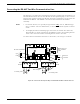
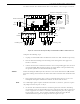
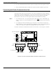
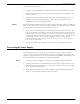
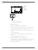
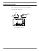

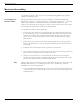
Table Of Contents
- 95 Series RFID System User’s Guide
- Table of Contents
- List of Figures
- Preface
- Introduction
- Reader R95 Installation and Connections
- Exciter E95 Installation and Connections
- Power Supply TRM95 Installation and Connection
- Configuration and Operation
- Before You Begin
- General Procedure Rules
- Setting Up the Reader/PC Connection
- Reader’s Power-up Sequence
- Learning Procedure (Optional)
- Resetting the Reader
- Checking the Reader’s Basic Parameters
- Setting Up the Exciter’s Address
- LF Transmitter Output
- Configuring the Reader
- Setting Up the Carrier Threshold
- Setting Up the Exciter’s Test-Tag
- Setting Up the Real Time Clock
- Configuring the Reader’s Application Parameters
- Configuring the Reader’s Network Parameters
- Storing the Reader’s Configuration
- Reader - Final Setup
- 95 Series RFID System - Final Test
- Programming and Testing the Transponder T95
- Troubleshooting
- Specifications
- Transponder T95 Messages
- Excitation Modes
- Reader Software Upgrade Procedure
- Glossary
- Index

Connecting the Exciter Communication Line
2-6 Reader R95 Installation and Connections
6. To select with the RS-485 interface, place the jumper P2 between pins 2-3 of J2.
7. Plug terminal blocks TB4 and TB6 into connectors TB3 and TB5 respectively.
Connecting the Exciter Communication Line
Two separate RS-485 two-wire interfaces are used to communicate between Readers
and Exciters. For more information, see the 95 Series RFID System Technical Guide.
The RS-485 connectors and jumpers for these lines are located on the Controller
Board CTL95. The CTL95 is the top board of the Reader Module Assembly.
Notes 1. For the RS-485 line, use specially designed cables only
, such as, BELDEN type
9842, or similar. For more information, see the 95 Series RFID System Technical
Guide.
2. To simplify the RS-485 multidrop-type connection, the two RS-485 connectors,
TB4 and TB6, are wired in parallel on the MBD95. Connect the incoming RS-485
cable to one connector and the outcoming RS-485 cable to the other.
To connect the RS-485 communication lines to the Reader, refer to Figure 2-4 below.
Figure 2-4: Connections and Jumper Settings for the Exciter Communication Line
A1 B1 G A2 B2
Out-coming cable
In-coming cable
A1 B1 G A2 B2
J2
J1
M
a
t
h
e
r
b
o
a
r
d
M
B
D
9
5
Controller CTL95
RS-485 Termination
RS485
RS485
TB6
TB4
Open
Open
Load
Load
P1
1
1
P2
RS485_CMDRS485_SGNRS485_CMD RS485_SGN