
User's Manual
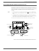
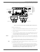
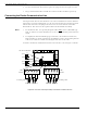
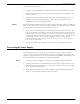
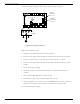

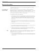
Table Of Contents
- 95 Series RFID System User’s Guide
- Table of Contents
- List of Figures
- Preface
- Introduction
- Reader R95 Installation and Connections
- Exciter E95 Installation and Connections
- Power Supply TRM95 Installation and Connection
- Configuration and Operation
- Before You Begin
- General Procedure Rules
- Setting Up the Reader/PC Connection
- Reader’s Power-up Sequence
- Learning Procedure (Optional)
- Resetting the Reader
- Checking the Reader’s Basic Parameters
- Setting Up the Exciter’s Address
- LF Transmitter Output
- Configuring the Reader
- Setting Up the Carrier Threshold
- Setting Up the Exciter’s Test-Tag
- Setting Up the Real Time Clock
- Configuring the Reader’s Application Parameters
- Configuring the Reader’s Network Parameters
- Storing the Reader’s Configuration
- Reader - Final Setup
- 95 Series RFID System - Final Test
- Programming and Testing the Transponder T95
- Troubleshooting
- Specifications
- Transponder T95 Messages
- Excitation Modes
- Reader Software Upgrade Procedure
- Glossary
- Index

Connecting the Power Supply
2-8 Reader R95 Installation and Connections
To connect the power supply to Reader R95, refer to Figure 2-5 below.
Figure 2-5: Power Supply Connections
Complete the following steps:
1. Unplug terminal block TB2 from its connector TB1.
2. Run the power supply cable through the cable grip into the Reader’s enclosure.
3. Connect the power wires to the TB2 pins marked with the “~”symbol.
4. Connect the main ground connection to the TB2 pin marked with the ground
symbol.
5. Switch on the power supply.
6. Check the voltage on terminal block TB2 (between pins marked with the “~”
symbol).
7. Plug terminal block TB2 into its connector TB1.
8. Re-check the voltage on the terminal block TB2 in Step 6.
9. Check the MBD95 to see whether the green POWER LED goes ON, and the red
DATA LED stays ON continuously for 6-7 seconds and then turns OFF.
10. Switch off the power supply.
DATA
Red LED
M
a
t
h
e
r
b
o
a
r
d
M
B
D
9
5
Controller CTL95
TB2
~
~
POWER
POWER
Green LED
12Vac 12Vac