
User's Manual
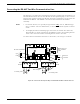
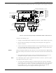
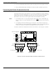
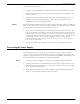
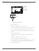
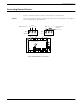

Table Of Contents
- 95 Series RFID System User’s Guide
- Table of Contents
- List of Figures
- Preface
- Introduction
- Reader R95 Installation and Connections
- Exciter E95 Installation and Connections
- Power Supply TRM95 Installation and Connection
- Configuration and Operation
- Before You Begin
- General Procedure Rules
- Setting Up the Reader/PC Connection
- Reader’s Power-up Sequence
- Learning Procedure (Optional)
- Resetting the Reader
- Checking the Reader’s Basic Parameters
- Setting Up the Exciter’s Address
- LF Transmitter Output
- Configuring the Reader
- Setting Up the Carrier Threshold
- Setting Up the Exciter’s Test-Tag
- Setting Up the Real Time Clock
- Configuring the Reader’s Application Parameters
- Configuring the Reader’s Network Parameters
- Storing the Reader’s Configuration
- Reader - Final Setup
- 95 Series RFID System - Final Test
- Programming and Testing the Transponder T95
- Troubleshooting
- Specifications
- Transponder T95 Messages
- Excitation Modes
- Reader Software Upgrade Procedure
- Glossary
- Index

Mechanical Assembling
3-2 Exciter E95 Installation and Connections
Mechanical Assembling
To assemble the Exciter E95, refer to the assembly drawing (M900121), and then
complete the following steps.
Assembling the LF
Antenna for E95
Theantennaframeconsistsoffiveseparatesegments,eachwiththefollowing
dimensions: two pieces - 0.4m long, two pieces - 2.0m long, and one piece - 1.0m long.
Each segment includes an aluminum tube with an internal rubber hose. The
segments are joined together using plastic corners. The antenna cable (7-wire cable)
runs through the rubber hoses inside the aluminum tubes.
To assemble the antenna, do the following:
1. Starting with one side of the antenna frame that is beside the plastic enclosure
(0.4 m segment), place the corresponding rubber hose inside the aluminum tube,
and run the antenna cable through the rubber hose. Run the cable through a
plastic corner, and secure the plastic corner inside the aluminum tube using a
rubber mallet.
2. Repeat Step 1 for each side of the frame, finishing with the last short segment
(0.4m). You should have a 1x2m rectangular aluminum frame with the antenna
cable inside.
3. Terminate the antenna frame with the plastic base connectors.
4. Place the 90° brackets on each ends of the frame, and secure the frame against the
plastic enclosure using M6 screws, washers and nuts.
5. Connect the antenna frame to the ground lead on the board, by securing the
terminal lug of the ground lead on the EXT95SC electronic board with one of the
M6 screws, as shown on the assembly drawing 600406.
Note Always ensure that the ends of the antenna cable inside the plastic enclosure have the
following dimensions: one - 110mm long and the other - 360mm long. For more
information, see the drawing 600406.
6. Use the self-drill screws (M3.5x9.5) to secure the 1 inch square aluminum tube in
each corner of the LF antenna frame, and to secure the 90° brackets against the
aluminum tubes.