
User's Manual

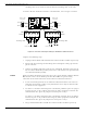
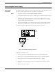


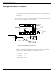
Table Of Contents
- 95 Series RFID System User’s Guide
- Table of Contents
- List of Figures
- Preface
- Introduction
- Reader R95 Installation and Connections
- Exciter E95 Installation and Connections
- Power Supply TRM95 Installation and Connection
- Configuration and Operation
- Before You Begin
- General Procedure Rules
- Setting Up the Reader/PC Connection
- Reader’s Power-up Sequence
- Learning Procedure (Optional)
- Resetting the Reader
- Checking the Reader’s Basic Parameters
- Setting Up the Exciter’s Address
- LF Transmitter Output
- Configuring the Reader
- Setting Up the Carrier Threshold
- Setting Up the Exciter’s Test-Tag
- Setting Up the Real Time Clock
- Configuring the Reader’s Application Parameters
- Configuring the Reader’s Network Parameters
- Storing the Reader’s Configuration
- Reader - Final Setup
- 95 Series RFID System - Final Test
- Programming and Testing the Transponder T95
- Troubleshooting
- Specifications
- Transponder T95 Messages
- Excitation Modes
- Reader Software Upgrade Procedure
- Glossary
- Index

LF Antenna Connections
Exciter E95 Installation and Connections 3-3
LF Antenna Connections
The LF antenna is a 7-turn loop coil with the tap at the first turn. To create this
multiturn loop and the proper tap connection, complete the following steps:
1. Positiontheantennacableinsidetheplasticboxasshownintheassembly
drawing 600406. Cut the end closest to the terminal block - 110mm long, and the
other - 360mm long.
2. Remove 80mm of the outside cable jacket, and strip about 8mm from each
conductor isolation.
3. Using a screwdriver, connect the antenna cable conductors in the terminal block
as shown in Figure 3-1 below.
Figure 3-1: LF Antenna Connections
Connecting the RS-485 Communication Lines
The RS-485 connectors and jumpers are located on the Exciter Slave EXT95SC
assembly placed inside the plastic enclosure (see the assembly drawing M900121).
Two separate RS-485 two-wire lines are used to transmit data from/to the Reader. For
detailed information on the RS-485 two-wires interface (half-duplex), see the 95 Series
RFID System Technical Guide.
Notes 1. For the RS-485 line, use specially designed cables only
, such as BELDEN type
9842, or similar. For more information, see the 95 Series RFID System Technical
Guide.
2. To simplify the RS-485 multidrop-type connection, the two RS-485 connectors,
TB4 and TB6 are wired in parallel on the EXT95SC board. Connect the RS-485
1
2
BLACK
WHITE
RED
BROWN
GREEN
BLACK
RED
BROWN
BLUE
ORANGE
ORANGE
GREEN
BLUE
WHITE
Black
Red
White
From Exciter
EXT95SC
Assembly
7 Conductors
Antenna Cable
Ends
7
8
3
4
5
6
Terminal Block